3-29
Performance Tests
Multiple PDH Transmitter Outputs (Options UHC, [US6])
51. Repeat steps 49 and 50 with the Oscilloscope Channel 1 connected to SIGNAL
OUT 2 and SIGNAL OUT 3 in turn.
8.448 Mb/s Additional Output Delay
52. Connect the PDH SIGNAL OUT 1 port to the Oscilloscope Channel 1. Set the
Oscilloscope termination to 1MΩ.
53. Connect the PDH SIGNAL OUT 2 port to the Oscilloscope Channel 2. Set the
Oscilloscope termination to 1MΩ.
54. Check that the pulse on Channel 2 is 4 bits delayed with respect to the pulse on
Channel 1.
55. Disconnect the SIGNAL OUT 2 port from the oscilloscope and connect the
SIGNAL OUT 3 port to the oscilloscope Channel 2.
56. Check that the pulse on Channel 2 is 8 bits delayed with respect to the pulse on
Channel 1.
57. Disconnect the SIGNAL OUT 3 port from the oscilloscope and connect the
SIGNAL OUT 4 port to the oscilloscope Channel 2.
58. Check that the pulse on Channel 2 is 12 bits delayed with respect to the pulse on
Channel 1.
59. Ensure that the ratio of +ve and -ve pulse amplitudes is between 0.95 and 1.05.
60. Ensure that the ratio of +ve and -ve pulse widths is between 0.95 and 1.05.
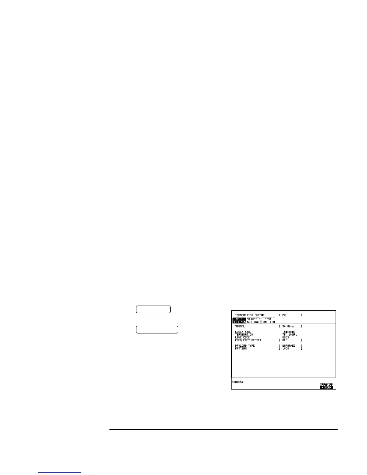
34.368 Mb/s Output Pulse
61. Connect the PDH SIGNAL OUT 2 port to the Oscilloscope Channel 1.
62. Press and set up the
display as shown opposite.
63. Press on the
oscilloscope.
64. Adjust the Oscilloscope Timebase and
Delay to position the positive peak pulse
amplitude at mid-pulse-width point in the
centre of the screen.
65. Measure the peak pulse amplitude at mid-pulse-width using the Oscilloscope and
verify that this is between 0.900V and 1.100V.
TRANSMIT
AUTOSCALE

 Loading...


