B-7
Appendix B - Fitting/Calibrating/Testing New Modules
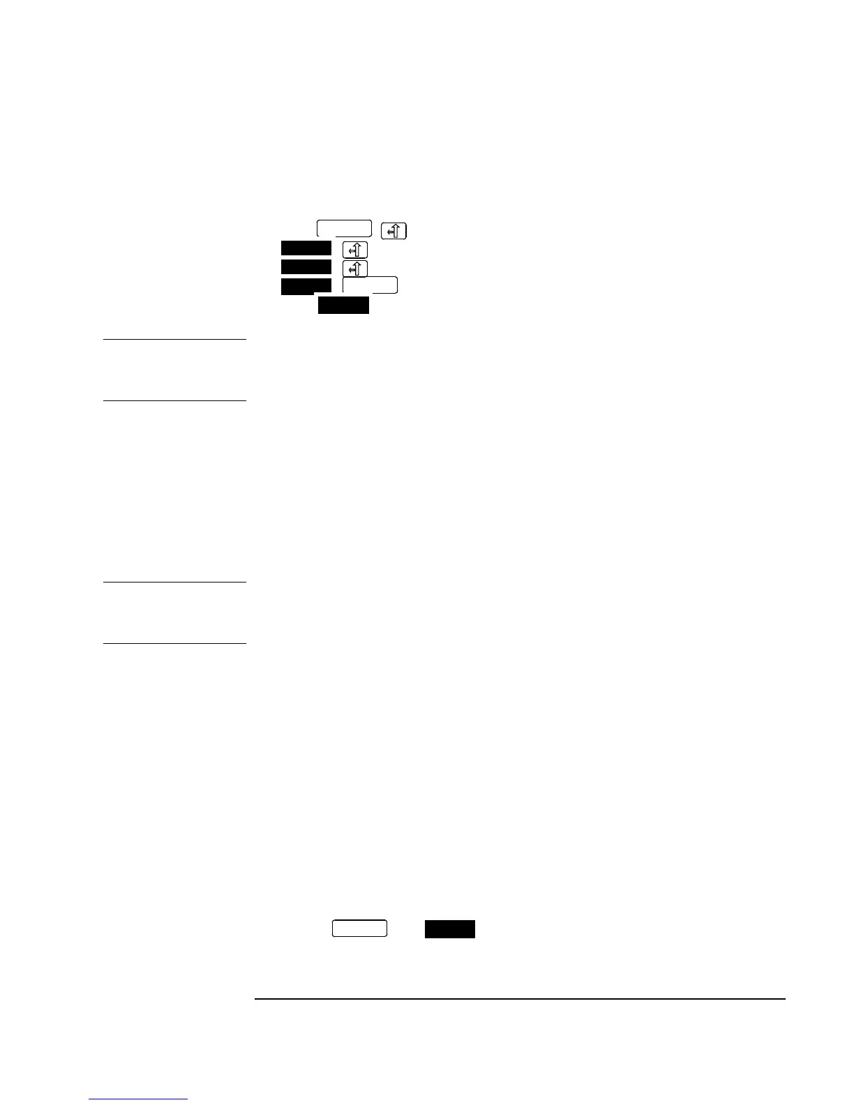
4. Make the following key sequence on the HP 37717C to obtain the MODULE
DEBUG display.
Press ;
;
;
;.
Press until MODULE DEBUG appears in the softkey menu.
CAUTION When using the MODULE DEBUG display, only modify parameters shown below.
Altering other parameters can cause damage to the instrument - prevent accidental
damage by leaving the Module Debug Page after setting up.
5. Press MODULE DEBUG and select MODULE [PDH MODULE] on the Display.
6. Select VCO CONTROL MODE [FIXED].
7. Select MODULE [JITTER MODULE] on the Module Debug Display.
8. Select TX CALIBRATION [ON].
9. Select RX CALIBRATION [OFF].
CAUTION The previous pre-adjustment sequence will need to be performed again if power is
cycled during Jitter Calibration, as MODULE DEBUG parameters return to default
values when instrument power is cycled.
Jitter Transmitter Calibration Procedure
1. Connect the HP 37717C Transmitter Output to the Spectrum Analyzer via the
75Ω/50Ω Matching Pad.
2. Set the Spectrum Analyzer as follows:
Centre Frequency 2048kHz
Reference Level 0dBm
Video Bandwidth 1kHz
Frequency Span 100kHz
Sweep Time 1.0 seconds
Resolution Bandwidth 100Hz
3. Press the then twice. Select the CALIBRATION function.
OTHER
MORE
MORE
MORE
OTHER
MORE
OTHER
MORE

 Loading...


