3-154
Performance Tests
Wander/Slips Measurement (Options UHN, [US9], A1M [A1Q], A1N
[A1R], A1P [A1S], A3L [A3M], A3V [A3W], A3N [A3P])
Description
In the first part of the test the HP 37717C Transmitter output is connected to the
Receiver Data and Reference Inputs simultaneously. The Wander measurement
result should be zero with this configuration since both inputs are effectively in
phase at the same frequency. This tests the wander measurement accuracy and the
Timing Reference Input circuitry (Balanced and Unbalanced data) as the wander
counters are latched by a division of the Reference Input and used to count the
received input bits.
In the second part of the test Wander and Slips measurements are verified using two
Clock Sources - one as input to the Receiver port and the other as input to the
Reference port. The sources are locked together but with one source offset by a
known frequency. This provides a known number of Bit Slips which are counted and
displayed by the HP 37717C as Frame/Bit Slips and Wander.
Equipment Required
Procedure
1. Recall the HP 37717C DEFAULT SETTINGS as shown on 3-2. Select
TRANSMITTER AND RECEIVER [COUPLED].
Wander Accuracy
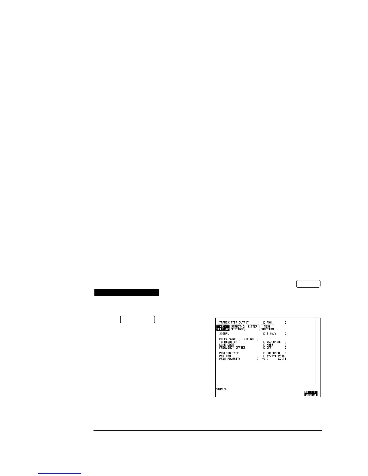
2. Press and set up the
display as shown opposite.
Synthesizer (2 off) : HP 3325B
120/75Ω Bal/Unbal Converter : HP 15508C
T Connector : HP 1250-0781
OTHER
SETTINGS CONTROL
TRANSMIT

 Loading...


