Item Specications
Installation mode Floor-mounted
Application environment Applicable to class C environments, but not to
class D environments
3.6 ETP48600-C5B1
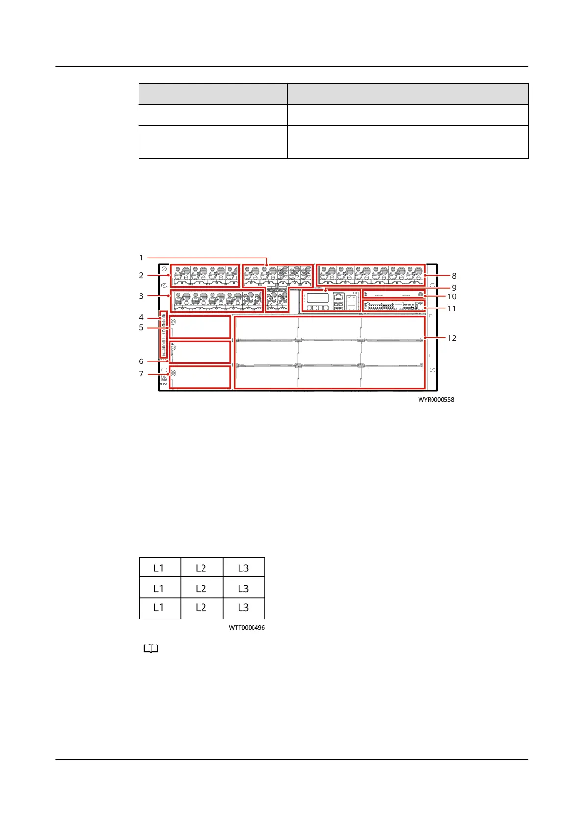
Figure 3-12 ETP48600-C5B1 interior
(1) LLVD2 circuit breakers
(2) Expansion circuit breakers (3) LLVD1 circuit breakers
(4) Ground screw (5) Space for the AC output
module
(6) Space for AC input module
1
(7) Space for AC input module
2
(8) Battery circuit breakers (9) SMU02C
(10) Space for the expansion
module
(11) UIM05D1 (12) Space for modules
Figure 3-13 Phase layout in the module installation space
● Refer to the phase layout when installing modules to ensure the balance of phases.
● PSUs, BCUs, and M48500N1 can be installed in the module installation space.
● Install modules from top to bottom and from left to right in the following sequence:
PSU, BCU, and M48500N1.
● The expansion module installation space supports communications expansion modules
and DG expansion modules.
PowerCube 1000 (STC, Saudi Arabia, ICC800-A1-C2,
ESC800-A1)
Installation Guide 3 Component
Issue 02 (2021-09-28) Copyright © Huawei Technologies Co., Ltd. 31
 Loading...