291
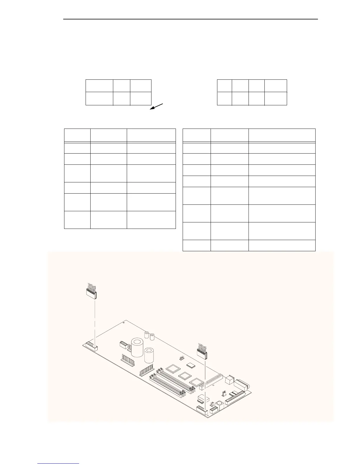
Main Wire Harness Test Tables
Device P106 Pins Normal
LRIB M 2, 4 and 6,8 7.2 - 8.8 Ω
PLAT M 1, 3 and 5, 7 1.35 - 1.65 Ω
LRP 10, 12 Open across pins
Short across post
CCF 9, 11 4.6 KΩ
PMD 14, 16
18, 20
8 Meg Ω
Open
POD 13, 15
17, 19
8 Meg Ω
Open
P106
P107
CCF = Card Cage Fan
LRIB M = Left Ribbon Motor
LRP = Left Ribbon Guide
PLAT M = Platen Open Motor
PMD = Paper Motion Detector (Switch)
POD = Paper Out Detect (Switch)
8 6 4 2
7 5 3 1
12 1020 18 16 14
11 919 17 15 13
LRIB M
PLAT M
LRP
CCF
PMD
POD
Pin No.
7 5 3 115 1319 17
RRIB M
PAPR M
HBF
EHF
CVO
MPU
RRP
PLO
CVO = Cover Open Switch
EHF* = Exhaust Fan
HBF = Hammer Bank Fan
MPU = Magnetic Pickup
PAPR M = Paper Feed Motor
PLO = Platen Open (Switch)
RRIB M = Right Ribbon Motor
RRP = Right Ribbon Guide
* Only in cabinet models
Device P107 Pins Normal
RRIB M 2, 4 and 6,8 7.2 - 8.8 Ω
PAPR M 1, 3 and 5, 7 0.417 - 0.681 Ω
HBF 10, 12 2.7 KΩ
EHF 9, 11 4.6 KΩ
RRP 14, 16 Open across pins
Short across post
PLO 13, 15 Continuity: switch closed
Open: switch open
CVO 18, 20 Continuity: switch closed
Open: switch open
MPU 17, 19 670 Ω
P106 Connector P107 Connector
Resistance
Resistance
11 9
8 6 4 216 1420 18 12 10
Connectors are viewed
from the top, as seen
when plugged into CMX
controller board.
NOTE: For cable shell
connector assembly and
disassembly, see page 195.
 Loading...