52
Chapter 4 Printer Interface
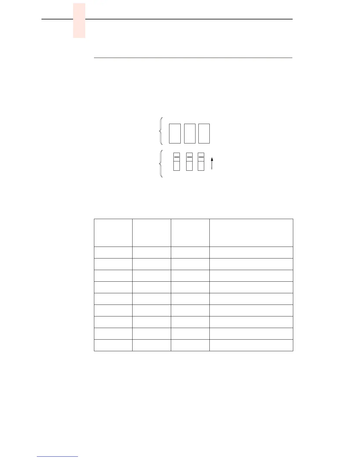
10Base2 And 10Base-T LEDs And DIP Switches
10Base2 and 10Base-T PrintNet Ethernet interfaces have three LEDs and
three DIP switches, as shown below. The indicators and switches are
adjacent to the data line connectors. LED patterns are defined in the table
below the illustration.
Status Indicator LEDs And DIP Switches
The PrintNet Ethernet assembly has a self test and two internally controlled
modes:
Power-on Self Test: A seven stage power-on self test performs diagnostics
on the Ethernet Interface processor, RAM, ROM, EEPROM, parallel port, and
network interface. The STAT, ERR, and NET LEDs indicate which test is
currently in progress.
Table 2. LED Pattern Indications
STAT
(System
Status)
ERR
(System
Error)
NET
(Data to
Network)
Mode
ON OFF ON RAM Test
ON OFF OFF ROM Test
ON ON OFF EEPROM Test
OFF ON ON Network Interface Test
OFF OFF ON PRN1 Test
FLASH OFF FLASH Run Mode
FLASH ON FLASH Auto Reset Mode
FLASH FLASH OFF Firmware Panic
ON FLASH ON Hardware Exception
123
OFF
Grn Red Grn
STAT ERR NET
Status
Indicators
DIP
Switches
(Default is all
switches OFF,
as shown.)
 Loading...