1
1
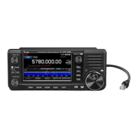
PANEL DESCRIPTION
q POWER SWITCH [POWER] (p. 31)
➥ Push to turn ON the transceiver power.
•First,conrmtheDCpowersourceisturnedON.
➥ Hold down for 1 second to turn OFF the power.
w TRANSMIT SWITCH [TRANSMIT] (p. 46)
Push to select transmit or receive.
•While transmitting, the MAIN Band’sTX/RX indica-
tor (i) lights red. Only on the satellite mode, the SUB
Band’s TX/RX indicator (!6) lights red.
•Whilereceivingorwhenthesquelchopens,theindica-
tor lights green.
e ANTENNA TUNER SWITCH [TUNER] (p. 159)
(Frequency band: HF/50 MHz)
➥ Push to turn the internal antenna tuner ON or
OFF (bypass).
•“ ” appears when the tuner is turned ON.
•Theinternalantennatunersettingscanbememo-
rized in each frequency band.
➥ Hold down for 1 second to manually start the an-
tenna tuner.
•Ifthetunercannottunetheantennawithin20sec-
onds, the tuning circuit is automatically bypassed.
r
ANTENNA•METER SWITCH [ANT•METER]
ANTENNA SWITCH Operation
(p. 158)
(Frequency band: HF/50 MHz)
➥ Push to select either the ANT1 or ANT2 connec-
tor.
METER SWITCH Operation
(p. 45)
(Frequency band: ALL)
➥ Hold down for 1 second to toggle the transmit
meter function between ALC, COMP and SWR.
t HEADPHONE JACK [PHONES]
Plug in standard stereo headphones (impedance: 8
to 16
ø).
•Outputpower:Morethan5mWwithan8ø load.
•Whenheadphonesareconnected,theinternalspeaker,
and any external speaker, are disabled.
•TheMAINandSUBBandaudiocanbemixedorsepa-
rated when using stereo headphones, depending on
the
“Phone Separate” option in the Set mode
. (p. 166)
y ELECTRONIC KEYER JACK [ELEC-KEY]
Plug in a bug or paddle type key to use the internal
electronic keyer for CW operation. (p. 22)
•SetthekeyertypetoELEC-KEY,BUGKEYorStraight
key in the “Keyer Type” item of the Keyer Set mode.
•Whenastraightkeyisconnected,“Straightkey”must
be selected in the “Keyer Type” item of the Keyer Set
mode. (p. 55)
•Astraightkeyjackislocatedontherearpanel.See
[KEY]onpages11and22.
•You can reverse the keyer paddle polarity (dot and
dash) in
the “Paddle Polarity” item
of
the Keyer Set mode.
(p. 55)
•Fourkeyermemorychannelsareavailableforyourcon-
venience. (p. 51)
u MICROPHONE CONNECTOR [MIC]
Plug in the supplied or an optional microphone.
•Seepage199forappropriatemicrophones.
•Seepage30formicrophoneconnectorinformation.
i MAIN BAND TX/RX INDICATOR
➥ Lights green when the squelch opens, or a signal
isreceivedontheMAINBand;lightsredduring
transmit.
➥ Blinks green when an off-frequency signal is re-
ceived, depending on the “FM/DV Center Error”
option in the Set mode. (p. 162)
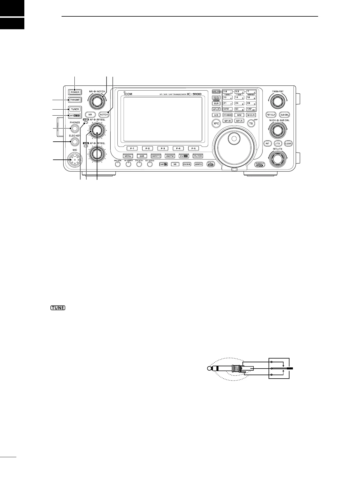
■ Front panel
t
i !0
y
q
e
r
u
o
!2
!1
w
 Loading...