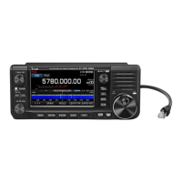
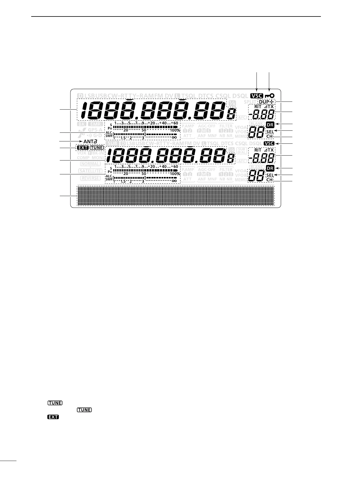
■ LCD display
15
1
PANEL DESCRIPTION
q FREQUENCY READOUTS
Displays the operating frequency.
•Whenthequicktuningicon“Z” is displayed, the fre-
quency changes in pre-set kHz or 1 MHz quick tuning
steps. (p. 38)
•Whenthequicktuningicon“Z” is not displayed, the fre-
quency changes in 10 Hz or 1 Hz steps. (pp. 37, 39)
w MULTI-FUNCTION METER INDICATION
➥Displays the signal strength while receiving.
➥Displays the relative output power, SWR, ALC or
compression levels while transmitting.
➥When the Meter Peak Hold function is ON, the
peak level of a received signal strength or the
output power is displayed for approximately 0.5
seconds.
e ANTENNA ICON (p. 158)
Displays which antenna connector is selected for
HF/50 MHz.
•“ANT1” appears when the [ANT1] connector is se-
lected.
•“ANT2” appears when the [ANT2] connector is se-
lected.
r ANTENNA TUNER ICONS (pp. 159, 160)
➥“ ” appears when the antenna tuner is
turnedON;“ ” blinks during tuning.
➥“ ” appears when the optional AH-4 external
antenna tuner is connected to the [ANT1] con-
nector, and [ANT1] is selected.
t FUNCTION DISPLAY (p. 19)
Shows the function of the function switches ([F1]–
[F5])
,
Set mode items and IF passband width.
y MEMORY CHANNEL READOUTS
Displays the selected memory channel.
u SELECT MEMORY CHANNEL ICON
➥ Appears when the selected memory channel is
set as a select memory channel.
(p. 151)
➥ Appears when the repeater can be selected as
the access repeater in the DR mode.
(p. 100)
i DR MODE ICON (p. 43)
Appears
when the DR mode is selected.
o RIT/∂TX ICONS (pp. 69, 81)
➥“RIT” appears when the RIT function is turned
ON.
➥“∂TX” appears when the ∂TX function is turned
ON.
➥ Shows the shift frequency of the RIT or ∂TX
function.
!0 VOICE SQUELCH CONTROL ICON (p. 146)
Appears when the VSC (Voice Squelch Control)
function is turned ON.
!1 DUPLEX ICON (p. 65)
“DUP+” appears when plus duplex, “DUP –” ap-
pears when minus duplex (repeater) operation is
selected.
!2 DIAL LOCK ICON (p. 77)
Appears when the Dial Lock function is turned ON.
 Loading...