18
183
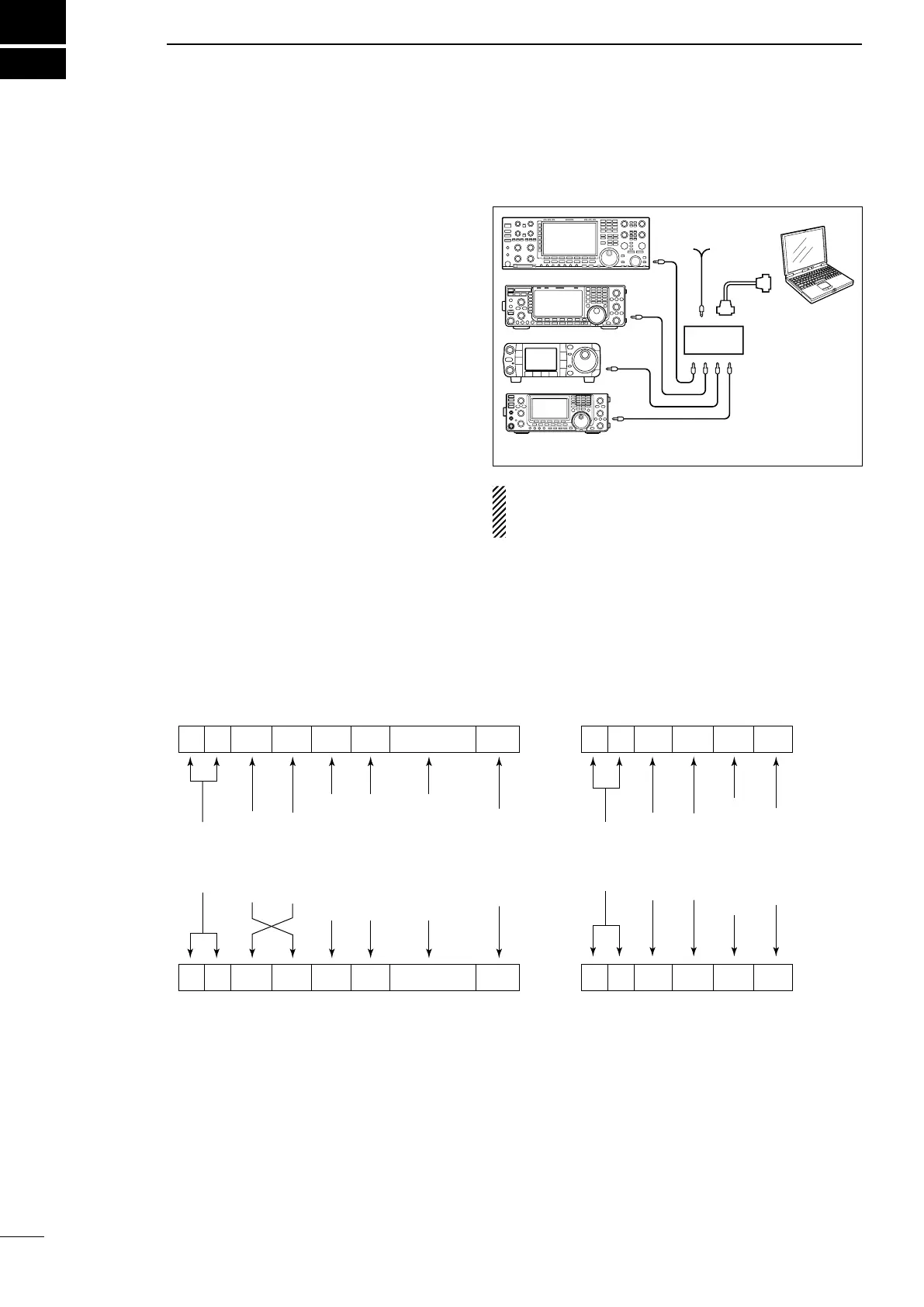
CONTROL COMMAND
■ Remote jack (CI-V) information
Controller to IC-9100
FE FE 7C E0 Cn Sc Data area FD
Preamble
code (fixed)
Transceiver’s
default address
Controller’s
default address
Command number
(see the command table)
Sub command number
(see the command table)
BCD code data such as
for frequency, memory
number entry
(see the data content description)
End of message
code
(fixed)
OK message to controller
FE FE E0 7C FB FD
FE FE E0 7C FA FD
Preamble
code
(fixed)
Controller’s
default address
Transceiver’s
default address
OK code
(fixed)
End of message
code (fixed)
NG message to controller
NG code
(fixed)
IC-9100 to controller
qwerty u
FE FE E0 7C Cn Sc Data area FD
qwerty u
D CI-V connection example
The transceiver can be connected through an optional
CT-17 c i -v l e v e l c o n v e r t e r to a PC equipped with an
RS-232C port. The Icom Communications Interface-V
(CI-V) controls the transceiver.
Up to 4 Icom CI-V transceivers or receivers can be
connected to the PC. See page 167 for setting the
CI-V condition using the set mode.
D Data format
The CI-V system can be operated using the following
data formats. Data formats differ depending on com-
mand numbers. A data area or sub command is added
to some commands.
IC-9100
9−15V DC
PC
ct-17
mini-plug cable
RS-232C
cable
When the transceiver is connected to a PC with the
USB cable (purchased separately), the optional
CT-17 is not required.
 Loading...