84
6
FUNCTIONS FOR TRANSMIT
1
2
3
4
5
6
7
8
9
10
11
12
13
14
15
16
17
18
19
20
21
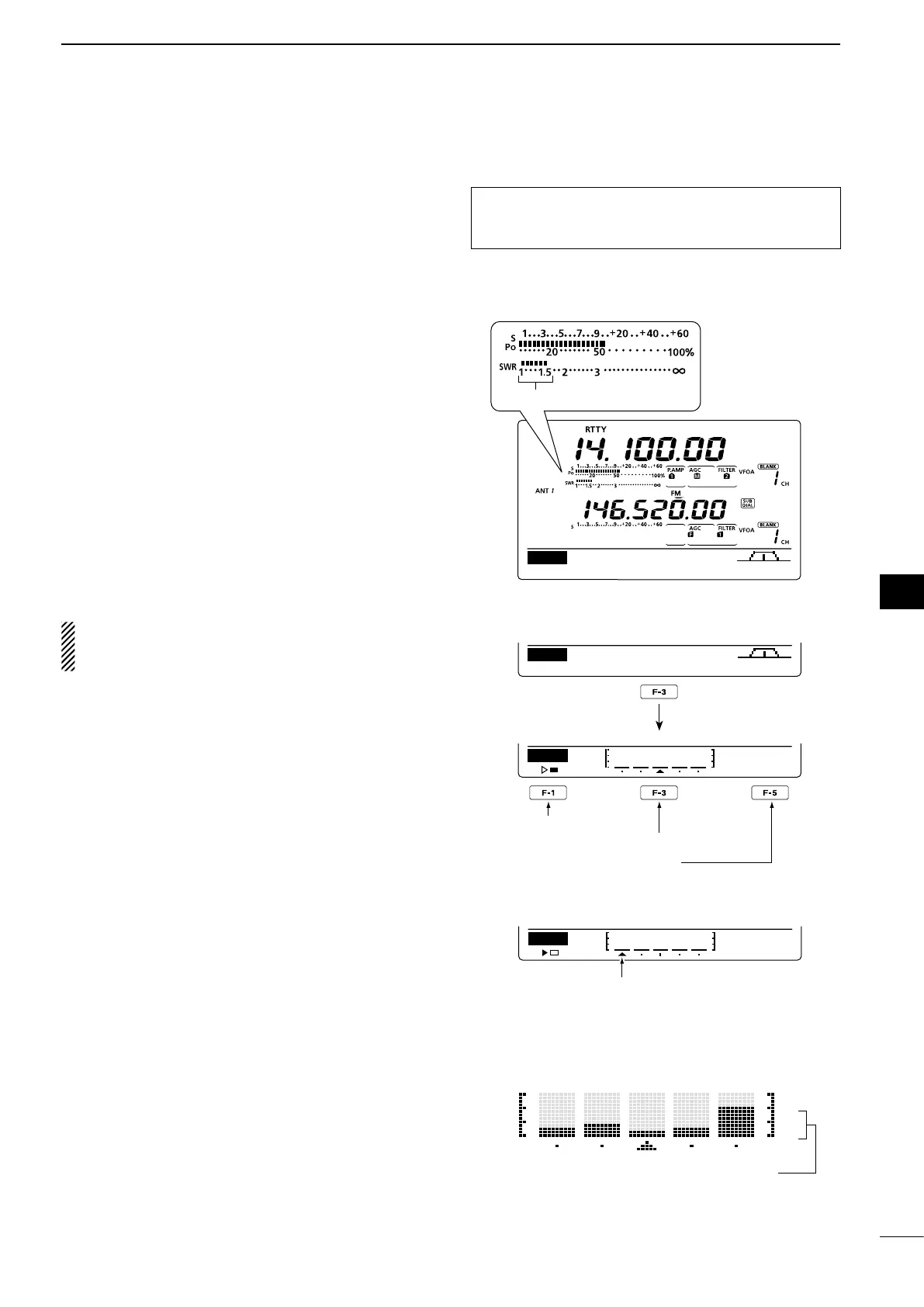
■ Measuring SWR
(Band: HF/50/144/430 MHz)
The IC-9100 has a built-in circuit for measuring an-
tenna SWR— no external equipment or special adjust-
ments are necessary.
The IC-9100 can measure SWR two ways— spot mea-
surement and plot measurement.
D Spot measurement
q Push [TUNER] once or twice to turn OFF the an-
tenna tuner.
wHold down [ANT•METER] for 1 second, one or
more times, to select the SWR meter.
ePush[CW/RTTY]onceortwicetoselecttheRTTY
mode.
r Push [PTT] on the microphone to transmit. (or
[TRANSMIT] on the transceiver).
t Rotate [RF POWER] clockwise past the 12 o’clock
positionformorethan30Wofoutputpower(30%).
y Read the SWR on the SWR meter.
u Release [PTT] to receive. (or push [TRANSMIT]
again)
The built-in antenna tuner matches the transmitter
to the antenna when the SWR is less than 3:1*.
* 2.5:1 in the 50 MHz frequency band.
D Plot measurement
Plot measurement allows you to measure the SWR
over an entire band.
q
P
ush [MENU] to display the “M2” screen (Menu 2),
then push [SWR](F-3).
•TheSWRgraphscreenappears.
w Rotate [RF POWER] clockwise past the 12 o’clock
positionformorethan30Wofoutputpower(30%).
e Set the center frequency for the SWR to be mea-
sured.
r Hold down [F-5] for 1 second one or more times to
select 10, 50, 100 or 500 kHz steps as the SWR
measuring step.
t Push [F-3] one or more times to select 3, 5, 7, 9, 11
or 13 steps as the number of measuring steps.
y Push [F-1] to start the measuring.
u Push [TRANSMIT] or hold down [PTT] on the mi-
crophone to measure the SWR.
•A frequency marker, “∫,” appears below the SWR
graph.
i Push [TRANSMIT] again or release [PTT] to move
the frequency marker and frequency indication to
the next frequency to be measured.
o Repeat steps u and i to measure SWR over the
entire frequency range.
!0 When the measured SWR is more than 1.5:1, ad-
just the antenna to match with the transceiver.
The best match is in this range.
MEM
SCAN
SWR
TCON
VSC
M2
SWR
10k
STEP
Push
Start measuring
Select number of SWR measuring steps
Select SWR measuring step
•Measuring (after pushing [F-1])
Frequency marker appears and moves
after measurement.
When measurement points are set
outside of the operable frequency
band, the frequency marker blinks.
Typical display SWR varying between 1 and 2,
full scale up to SWR 4.0:1.
— 1.0:1
— 1.5:1
— 2.0:1
— 3.0:1
The antenna SWR cannot be measured on the 1200
MHz frequency band*.
* The optional UX-9100 is required.
 Loading...