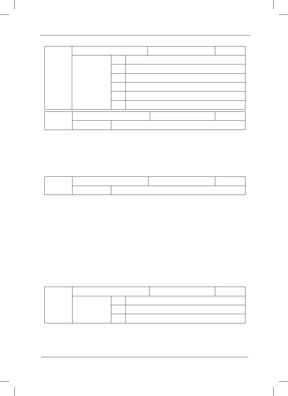
F2-09
Torque upper limit source Factory default value 0
Setup range
0 F2-10
1 AI1
2 AI2
3 AI3
4 PULSE setup
5 Communication setup
F2-10
Torque upper limit Factory default value 150%
Setup range 0%~ 200%
In the speed control mode, F2-09 is used to select the setup source of torque upper limit. When
setting via the analog value, 100% of the analog input setup corresponds to F2-10, and the
setup 100% corresponds to the rated torque of the motor matching the inverter.
In the torque control mode, torque upper limit source is the torque setup source. Torque upper
limit is the torque setup command.
F2-11
Encoder pulse number Factory default value 1024
Setup range 0 ~ 65535
It is used to set the number of pulses of each turn of encoder.
Caution: When the inverter controls the speed sensor vector control, it must set the pulse
number of the encoder correctly, or the motor will run abnormally. If normal operation cannot
be realized after correct pulse number of the encoder is set, exchange the connecting positions
of Phase A and Phase B of the encoder.
This group of function code is enabled only for the V/F control (F0-01=2) and is inactive for the
vector control.
V/F control is applicable to the general loads such as fan and pump or the applications where
one inverter drives multiple motors or the inverter power is one level lower or higher than the
motor power.
Group F3 V/F Control Parameters
F3-00
V/F curve setup Factory default value 0
Setup range
0 Straight V/F curve
1 Multiple-point V/F curve
2 Square V/F curve
The fan and pump loads may select square V/F control.
0: Straight V/F curve. It is suitable for common constant torque load.
1: Multiple-point V/F curve. It is suitable for the special loads such as dehydrator and centrifugal
 Loading...
