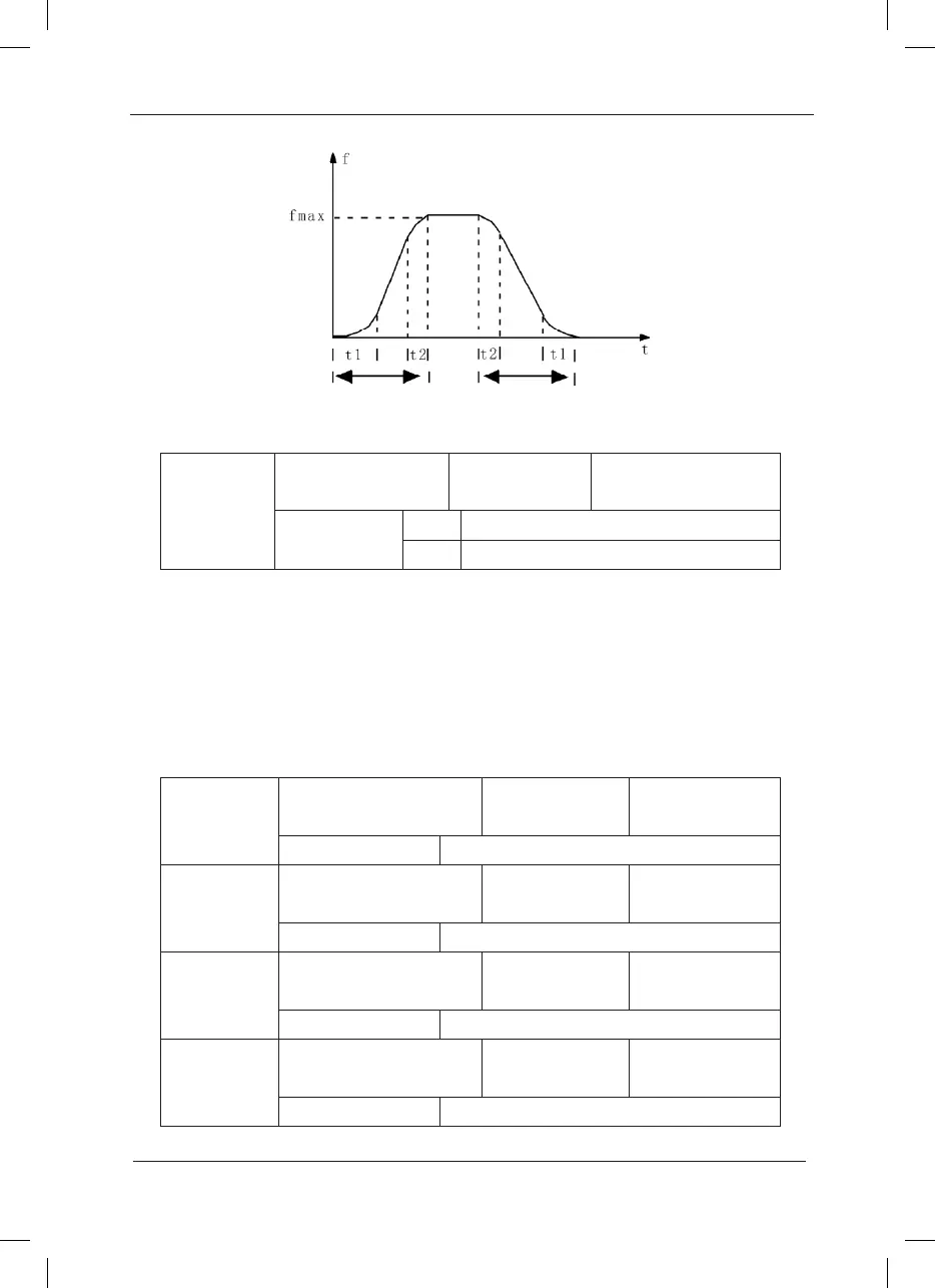
Fig.6-10 Schematic Diagram for S curve Acceleration/Deceleration
F6-10
Stop mode
Factory default
value
0
Setup range
0 Speed-down to stop
1 Free to stop
0: Speed-down to stop
After the stop command is enabled, the inverter reduces the output frequency in accordance
with the deceleration mode and the dened acceleration/deceleration time, and will stop after
the frequency reduces to zero.
1: Free stop
After the stop command is enabled, the inverter will terminate the output immediately. The load
will coast to stop according to the mechanical inertia.
F6-11
DC b ra ke b eg in ni ng
frequency at stop
Factory default
value
0.00Hz
Setup range 0.00Hz ~maximum frequency
F6-12
DC brake waiting time
at stop
Factory default
value
0.0s
Setup range 0.0s~ 36.0s
F6-13
DC b ra ke current at
stop
Factory default
value
0%
Setup range 0%~ 100%
F6-14
DC brake time at stop
Factory default
value
0.8s
Setup range 0.0s~ 36.0s
 Loading...
