Appendix B: Description of Long-line Drive PG Card (MD32PG3)
This PG card is connected to the adapter of Inovance inverter as differential encoder. It can be
applied in the situation with synchronous motor and induction motor close loop control.
When the synchronous motor is applied, it can connect to the UVW encoder of the rotor 1.
magnetic role, and the number of poles of the UVW encoder shall be equal to that of the
synchronous motor. Only when the number of poles is equal can they be used together.
When the induction motor is applied, it connects to the common differential encoder, and 2.
the UVW terminal needs no cable connection at this time.
It must use the encoder with operating power supply of 5V. 3.
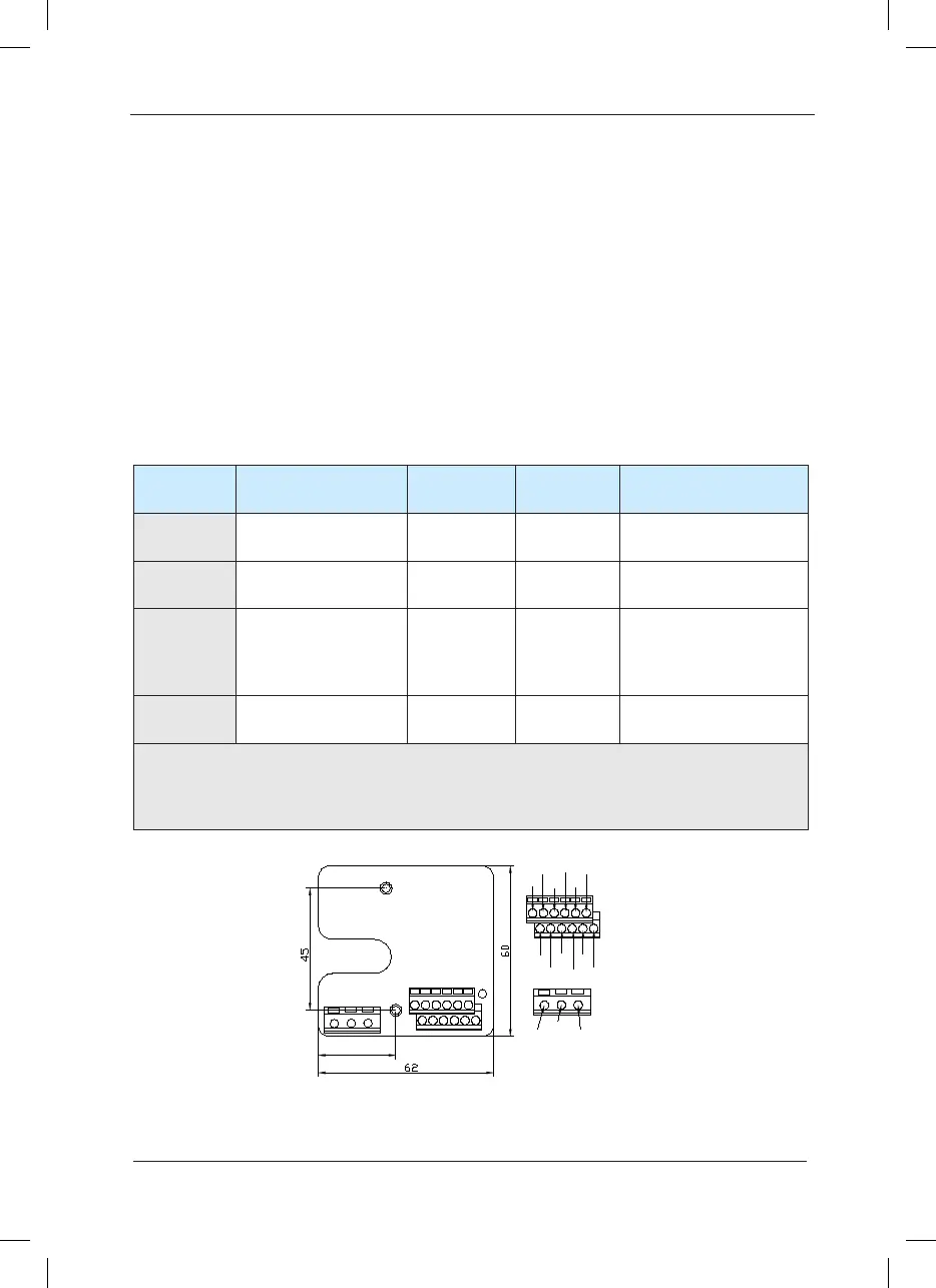
PG card terminal description: 4.
Appendix B: Table 1 PG Card Terminal Description
Function
Response
speed
Maximum
current
Remarks
+5V, COM
Operating power
supply of encoder
A+, A-,
B+, B-,
A/B signal of
encoder
0 to 80kHz ---
U+, U-,
V+, V-,
W+, W-,
UVW position signal
of encoder
0 to 10kHz ---
When the common
encoder is applied, this
terminal has no cable
connection.
OUT-A,
OUT-B
A/B signal output 0 to 80kHz 100mA Open collector signal
Caution:
It must use the encoder with operating power supply of 5V. 1.
The UVW encoder can also be used as common encoder. 2.
 Loading...
