Speed-up/speed-down time can select F0-17 and F0-18 and above three types of speed-up/
speed-down time. Their meanings are the same, and refer to F0-17 and F0-18 for the relevant
descriptions.
It can select speed-up/speed-down time 1 to 4 during the inverter running process via the
different combination of multifunctional digital input terminal DI. Please refer to F4-01 to F4-05.
F8-09
Skip frequency 1
Factory default
value
0.00Hz
Setup range 0.00Hz~ maximum frequency
F8-10
Skip frequency 2
Factory default
value
0.00Hz
Setup range 0.00Hz~ maximum frequency
F8-11
Skip frequency
amplitude 1
Factory default
value
0.00Hz
Setup range 0.00~ maximum frequency
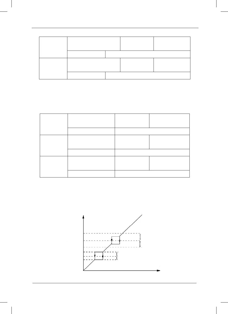
When the setup frequency is within the skip frequency range, the actual running frequency will
be in the skip frequency boundary close to the setup frequency.
It can make the inverter run away from the mechanical resonance point of the load through
setting the skip frequency. This inverter can set two skip frequency points. If the two skip
frequencies are set to zero, this function will be inactive.
Fig.6-11 Schematic Diagram of Skip Frequency
F8-07
Speed-up time 4
Factory default
value
20.00s
Setup range 0.0s~ 6500.0s
F8-08
Speed-down time 4
Factory default
value
20.00s
Setup range 0.0s ~ 6500.0s
 Loading...
