Power Level
Mounting Dimension
B A
≤15kW ≥100mm No requirements
18.5kW—30kW ≥200mm ≥50mm
≥37kW ≥300mm ≥50mm
Fig.3-1 MD320 Inverter Installation Diagram
3.1.2 Heat dissipation shall be taken into account during the mechanical installation.
Please pay attention the following items:
Install the inverter vertically so that the heat may be expelled from the top. However, 1)
the equipment cannot be installed upside down. If there are multiple inverters, parallel
installation is a better choice. In applications where the upper and lower parts of the
inverter need to be installed, please refer to Fig.3-1 “MD320 Inverter Installation Diagram”
and install an insulating splitter.
The mounting space shall be as indicated as the above gure, so as to ensure the heat 2)
dissipation space of the inverter. However, the heat dissipation of other devices in the
cabinet shall also be taken into account.
The installation bracket must be ame retardant.3)
In the applications where there are metal dusts, it is recommended to mount the radiator 4)
outside the cabinet. In this case, the space in the sealed cabinet shall be large enough.
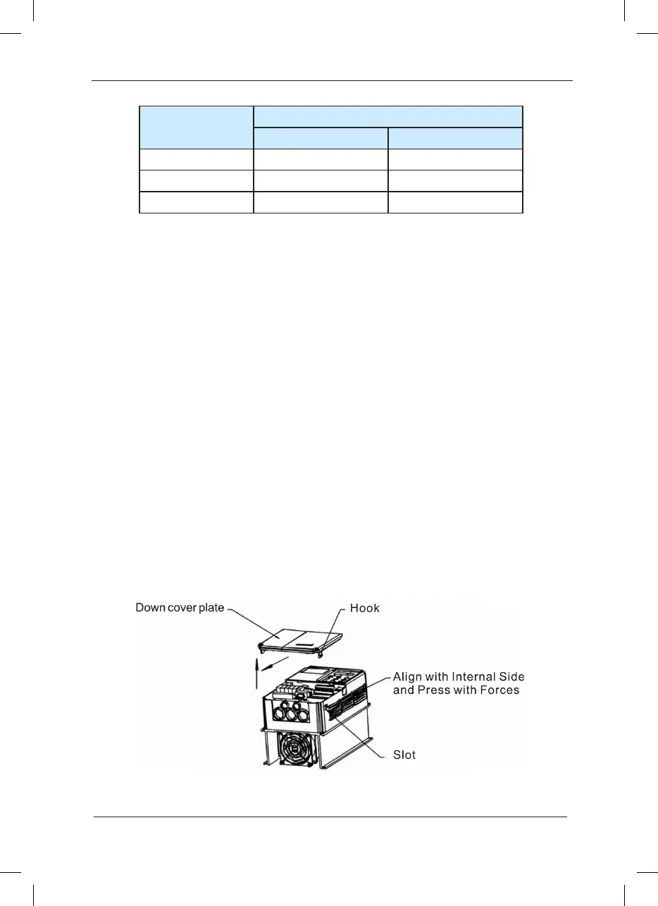
3.1.3 Removing and mounting the lower cover plate
The MD series inverter of less than 15kW employs plastic enclosure. Please refer to Figure 3-2
and Figure 3-3 for removing the down cover plate of the plastic enclosure. The hooker of the
lower cover plate is easy to pull out with tools by forces inside.
Fig.3-2 Removing the Lower Cover Plate of Plastic Enclosure
 Loading...
