F4-10
DI lter time Factory default value 4
Setup range 0 ~ 10
It is used to set the sensitivity of DI terminal. If the digital input terminal is vulnerable to
interferences and may cause error action, it can increase this parameter value to enhance the
anti-interference capability. However, this operation will reduce the sensitivity of DI terminal.
F4-11
Terminal command mode Factory default value 0
Setup range
0 Two-line mode 1
1 Two-line mode 2
2 Three-line mode 1
3 Three-line mode 2
This parameter denes four different modes of controlling the operation of the inverter via the
external terminals.
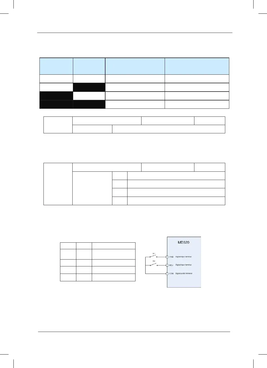
0: Two-line running mode 1: This mode is the most commonly used two-line mode. The forward/
reverse rotation of the motor is decided by the commands of FWD and REV terminals.
Fig.6-5 Two-line Running Mode 1
1: Two-line running mode 2: When this mode is adopted, REV is enabled terminal. The direction
is determined by the status of FWD.
Attached Table 2 MS Speed Function Description
Terminal 2 Terminal 1
Speed-up/speed-down
time selection
Corresponding Parameter
OFF OFF Speed-up time 1 F0-17 and F0-18
OFF ON Speed-up time 2 F8-03, F8-04
ON OFF Speed-up time 3 F8-05 and F8-06
ON ON Speed-up time 4 F8-07 and F8-08
K1 K2 Running Commanc
0 0 Stop
1 0 Forward Rotation
0 1 Reverse Rotation
1 1 Stop
 Loading...
