The setup length, actual length and number of pulses each meter are mainly used for xed
length control.
The length is calculated via the pulse signal input by the digital input terminal, and it needs to
set the corresponding input terminal to length count input terminal. It needs to use DI5 input
generally when the pulse frequency is relatively high.
Actual length=length count input number of pulses/number of pulses each meter
When the actual length FB-06 exceeds the setup length FB-05, the multifunctional digital output
terminal “Length Arrival Terminal” will output ON signal (refer to F5-04 function code).
FB-08
Setup counting value Factory default value 1000
Setup range 1 ~ 65535
FB-09
Designated counting value Factory default value 1000
Setup range 1 ~ 65535
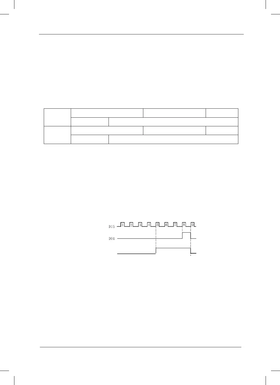
The counting value is input to the terminal input pulse signal via the counter in the digital input
terminal.
When the counting value reaches the setup counting value, the digital output terminal will
output signal of setup counting value arrival. The counter will stop counting.
When the counting value reaches the designated counting value, the digital output terminal will
output signal of designated counting value. The counter will continue counting till the “setup
counting value” is reached.
The designated counting value FB-09 shall not exceed the setup counting value FB-08.
This function is as shown the following gure:
Fig.6-17 Schematic Diagram for Setup Counting Value Reference and Designated Counting
Value Reference
Group FC MS Speed Function and Simple PLC Function
Simple PLC function is to perform automatic control on the MS frequency logic through a built-
in programmable controller (PLC) of the inverter. It can set running time, running direction and
running frequency so as to meet the process requirements.
This series of inverter can implement 16-segment variable control and has four types of
acceleration/deceleration time for selection.
When the setup PLC completes one cycle, it can output one ON signal via the multifunctional
output terminals DO1 and DO2 or multifunctional relay 1 and relay 2. Refer to F5-02 to F5-05