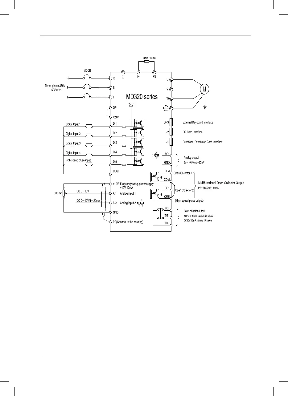
Fig. 3-6 Schematic Diagram for Three-phase Inverter Connection
Precautions are as follows:
1. Terminal
◎
refers to the main circuit terminal
,
Terminal ○ refers to the control circuit terminal.
2. The 0.75kW~15kW Auto unit is the standard conguration.
3. 7.5kW~55kW is build-in DC reactor.
4. The selection of the braking resistor is according to the user need. See the prototyping Guide
of braking resistor for details.
Schematic Diagram for Three-phase Inverter Connection:
 Loading...
