EasyManua.ls Logo

Inovance MD300 User Manual

Inovance MD300
204 pages
To Next Page IconTo Next Page
To Previous Page IconTo Previous Page
Page #63 background imageLoading...
Page #63 background image
Operation and Display MD320/MD320N User Manual
62
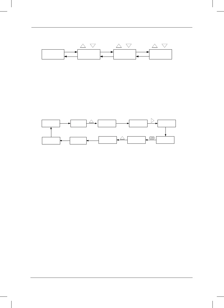
Fig.4-2 Operation Procedure of Three-level Menu
Caution: When operating on level 3 menu, press PRG key or ENTER key to return to
level 2 menu. The difference between PRG key and ENTER key is described as follows:
Pressing ENTER KEY will save the setup parameter and return to the level 2 menu and then
automatically shift to the next function code, while pressing PRG key will directly return to level
2 menu without saving the parameter, and it will return to the current function code.
Example: Modify the function code F3-02 from 10.00Hz to 15.00Hz. (The bold-type work
indicates the ashing bit.)
Fig.4-3 Example of parameter editing operation
In level 3 menu, if the parameter has no ashing bit, it indicates that the function code cannot
be modied. The possible reasons include:
1) The function code is an unchangeable parameter, such as actual detection parameter,
running record parameter, etc.
2) The function code cannot be modied in running status. It can be modied only after the unit
is stopped.
4.3 Shortcut Menu Operation Mode
The shortcut menu is set to facilitate the user to quickly view and modify the commonly used
function parameters. In the shortcut menu, the parameter is displayed in the form of “Uf3-02”,
which indicates the function parameter F-02. Parameter modication in the shortcut menu has
the same effect as the operation in the common programming status.
The shortcut menu can contain 16 function parameters at most. If there are 16 parameters and
the user wants to add more, it will display “FULL”. If “NULL” is displayed when entering the
menu, it indicates that the shortcut menu is null. The shortcut menu operation is limited by the
function code F7-03. When F7-3 is set to “0”, addition or deletion operation can be performed
on the shortcut menu. When F7-03 is set to “1”, the parameter option is locked and addition or
deletion operation is inactive.
The shortcut menu has stored the 16 common parameters by default for the convenience of the
user:
50.00 050.00F0-08F0
First-level menu Second-level menu Third-level menu
PRG/
ENTER
PRGPRG
PRG ENTER ENTER
Parameter Set
Modification
Function Code
Modification
Function Code
Modification
F3-00
F3
ENTER
F3-02
010 .00
010.00015.00
F3-03
ENTER
F3
PRG
50.00 F0
PRG
ENTER

Table of Contents

Question and Answer IconNeed help?

Do you have a question about the Inovance MD300 and is the answer not in the manual?

Inovance MD300 Specifications

General IconGeneral
BrandInovance
ModelMD300
CategoryInverter
LanguageEnglish

Summary

Safety and Precautions

Safety Precautions

Detailed safety measures for handling the inverter before, during, and after installation.

Product Information

Physical Appearance and Dimensions

Routine Repair and Maintenance

Instructions on Warranty

Mechanical and Electric Installation

Mechanical Installation

Guidelines for the physical installation and environmental requirements of the inverter.

Electrical Installation

Instructions for the electrical installation and connection of the inverter.

Main Circuit Terminals and Connections

Control Terminal and Connection

Operation and Display

Description of Function Code Viewing and Modification Methods

How to navigate, view, and modify function codes and parameters.

Shortcut Menu Operation Mode

Method of Viewing Status Parameter

Automatic Motor Parameter Tuning

Function Parameter Table

Parameter Description

Group F1 Motor Parameters

Parameters for configuring motor characteristics and tuning.

Group F2 Vector Control Parameters

Parameters specific to the vector control operating modes.

Group F6 Start/Stop Control

Parameters controlling inverter start, stop, and braking behavior.

Group F9 Fault and Protection

Parameters for configuring motor overload, stall protection, and fault handling.

EMC Guide

Fault Diagnosis and Solution

Fault Alarm and Countermeasures

Lists common fault alarms and provides corresponding troubleshooting steps and countermeasures.

Common Fault and Resolution

Table listing common fault phenomena, their possible causes, and solutions.

Warranty Agreement

Related product manuals