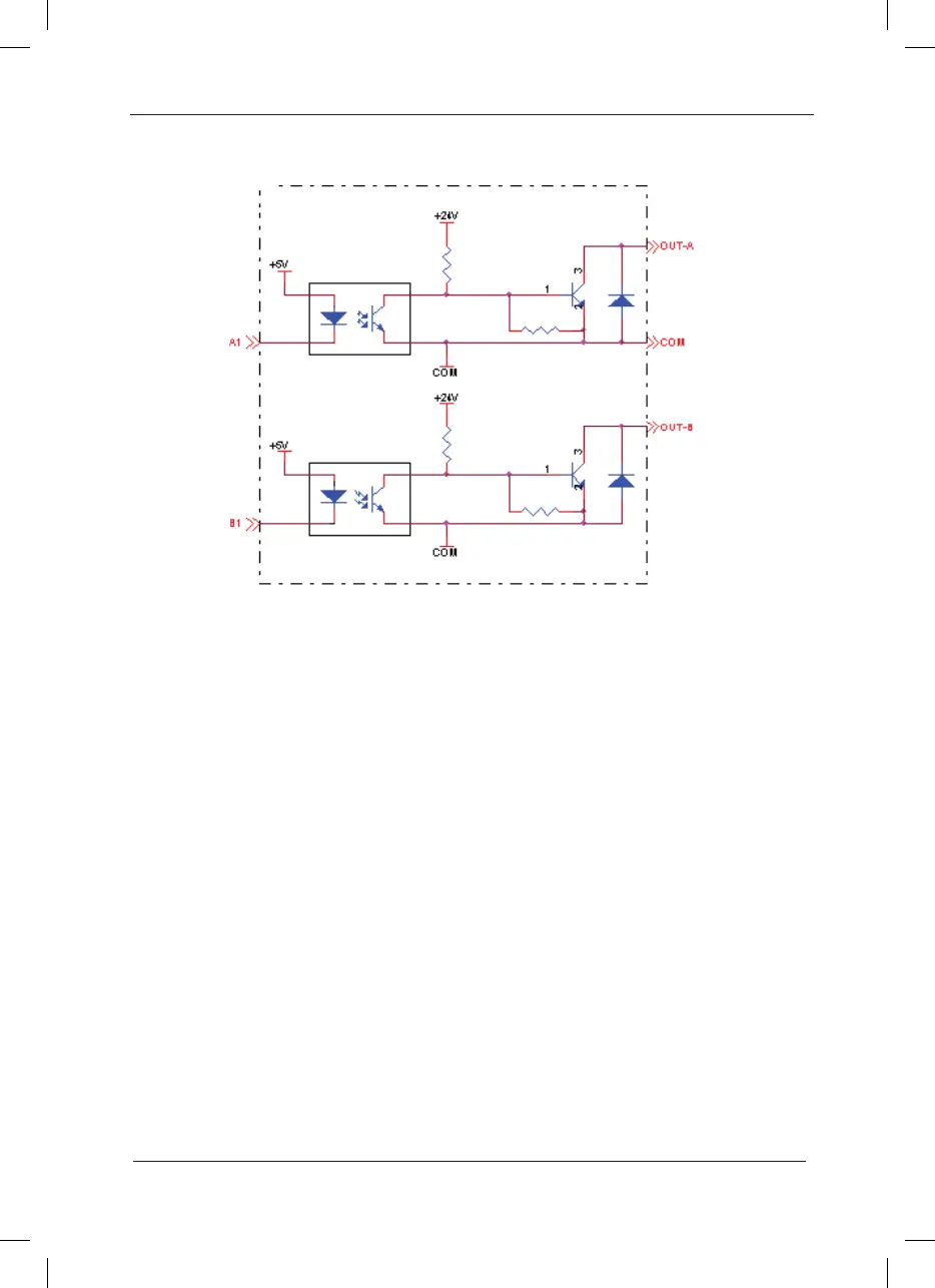
Appendix A: Fig.5 Schematic Diagram for Frequency Division Interface
A.2.4 Precautions
The PG card signal cables and the power cables shall be arranged separately, and parallel 1.
wiring is not allowed;
To avoid interferences on the encoder signal, please select the shielded cable as the PG 2.
card signal cable;
The shielding layer of the shielded cable of the encoder shall be earthed (e.g. the PE end 3.
of inverter) and must be earthed at single end so as to avoid interferences on the signal;
The length of shielded cable of the encoder shall be less than 80 meters. 4.
If the frequency division output of the PG card is connected to external user power supply, 5.
the voltage shall be less than 30V, or it will damage the PG card.
A.3 Application Connection
1. Schematic Diagram for the Connection of Collector Output Encoder
 Loading...
