8-11
CLOCK AND POWER MANAGEMENT UNIT
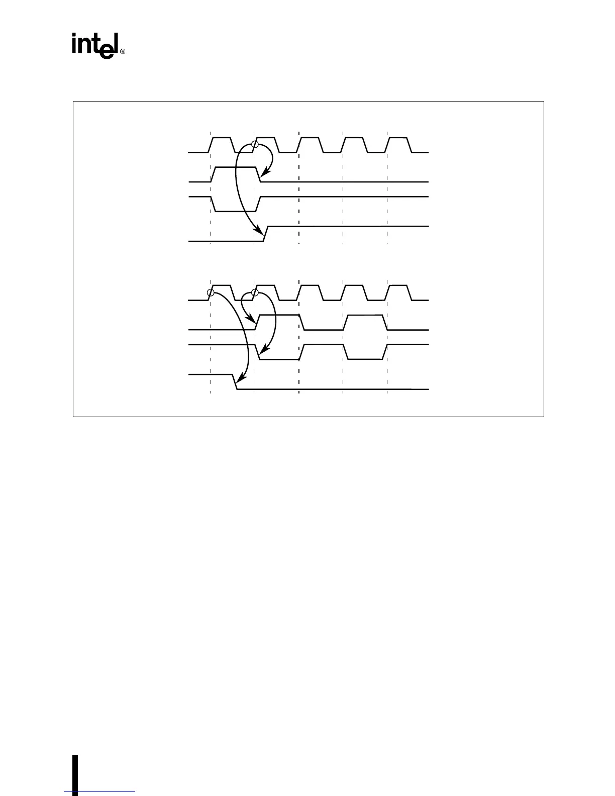
Figure 8-7. Timing Diagram, Entering and Leaving Powerdown Mode
8.4 DESIGN CONSIDERATIONS
This section outlines design considerations for the clock and power management unit.
8.4.1 Reset Considerations
External circuitry must provide an input to the RESET pin. The RESET input must remain high
for at least 16 CLK2 cycles to reset the chip properly.
The RESET pin signal is routed directly to the device’s bidirectional pins. Even in idle or power-
down, a device reset floats the bidirectional pins and turns on the weak pull-up or pull-down tran-
sistors.
The clock generation logic generates a synchronous internal RESET signal for the internal pe-
ripherals. If you need a synchronous RESET signal for other system components, you can use a
simple circuit such as the one shown in Figure 8-8 to generate it. Otherwise, the CPU does not
need a synchronous reset.
A2469-02
CLK2
PH2P/PH2C
PH1 PH2 ?
CLKOUT/PH1P/PH1C
PWRDOWN
?
CLK2
PH2P/PH2C
PH2 PH1 PH2
CLKOUT/PH1P/PH1C
PWRDOWN
PH1

 Loading...


