5-21
DEVICE CONFIGURATION
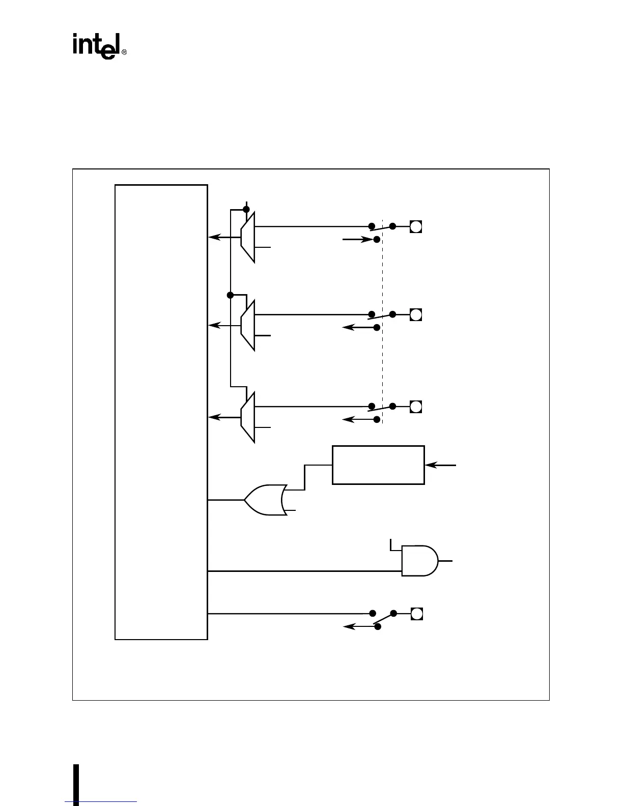
5.2.7 Core Configuration
Three coprocessor signals (ERROR#, PEREQ, and BUSY# in Figure 5-13) can be routed to the
core, as determined by bit 5 of the PINCFG register (see Figure 5-15). Due to signal multiplexing
at the pins, the coprocessor and Timer/counter2 cannot be used simultaneously.
Figure 5-13. Core Configuration
A2520-02
PEREQ
BUSY#
Core
0
1
PINCFG.5
† Alternate pin signals are in parentheses.
V
CC
ERROR#
ERROR#
(TMROUT2)†
From TCU
0
1
V
SS
PEREQ
(TMRCLK2)
To TCU
0
1
V
CC
BUSY#
(TMRGATE2)
To TCU
PINCFG.5
RESET
A20
To Chip-select Unit
and A20 Pin
PORT92.1
From Chip RESET Pin
RESET Timing
Generation
PORT92.0
LOCK#
LOCK#
(P1.5)
To/From I/O Port 1
0
1
0
1
0
1
1
0
P1CFG.5

 Loading...


