Intel386™ EX EMBEDDED MICROPROCESSOR USER’S MANUAL
D-38
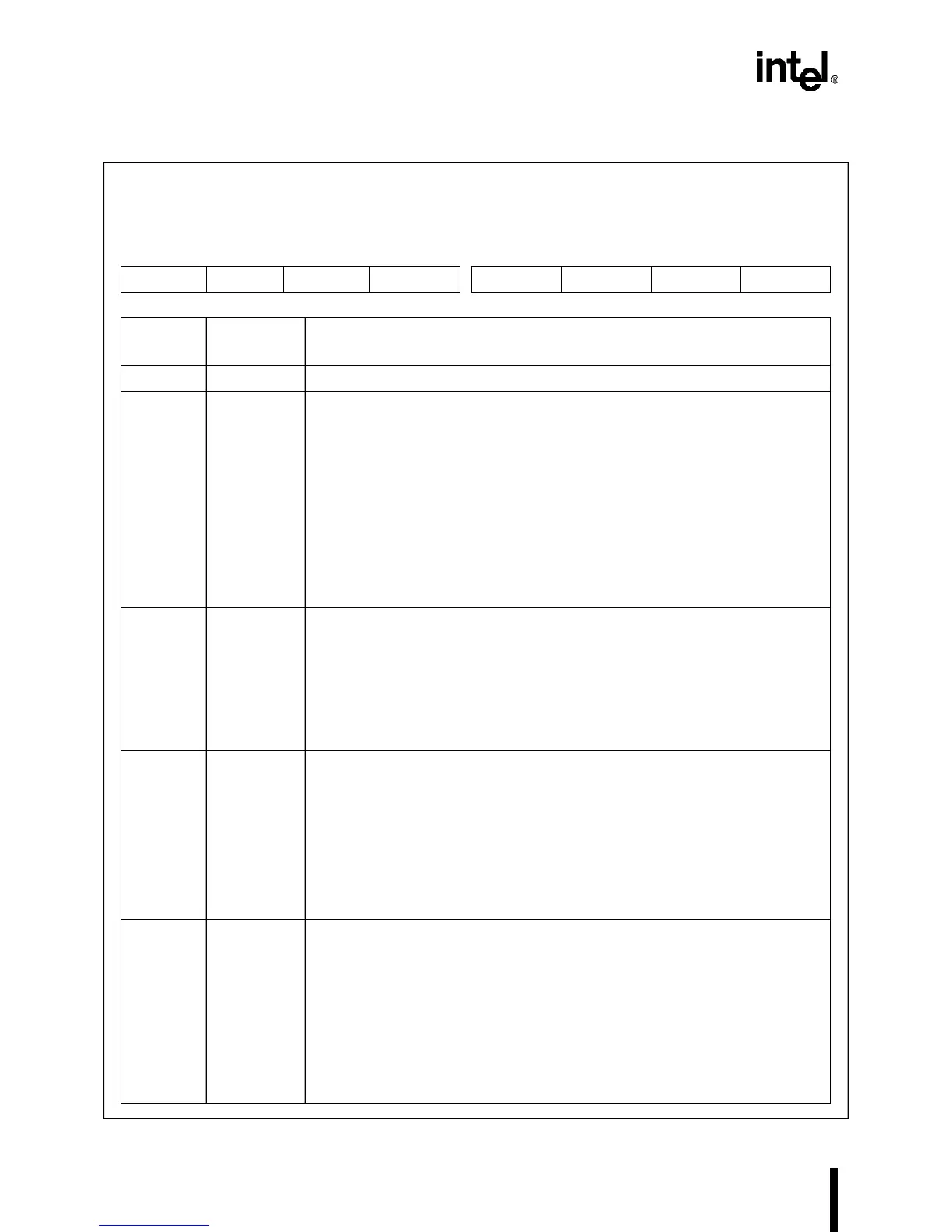
D.35 MCR
n
Modem Control
MCR0, MCR1
(read/write)
Expanded Addr:
ISA Addr:
Reset State:
MCR0 MCR1
F4FCH F8FCH
03FCH 02FCH
00H 00H
7 0
— — — LOOP OUT2 OUT1 RTS DTR
Bit
Number
Bit
Mnemonic
Function
7–5 — Reserved; for compatibility with future devices, write zeros to these bits.
4 LOOP Loop Back Test Mode:
0 = Normal mode
1 = Setting this bit puts the SIO
n
into diagnostic (or loop back test) mode. This causes
the SIO channel to:
• set its transmit serial output (TXD
n
)
• disconnect its receive serial input (RXD
n
) from the package pin
• loop back the transmitter shift register’s output to the receive shift register’s input
• disconnect the modem control inputs (CTS
n
#, DSR
n
#, RI
n
#, and DCD
n
#) from the
package pins
• force modem control outputs (RTS
n
# and DTR
n
#) to their inactive states
• connects MCR
n
bits to MSR
n
bits
3–2 OUT2:1 Test Bits:
In diagnostic mode (bit 4=1), these bits control the ring indicator (RI
n
) and data carrier
detect (DCD
n#
) modem inputs. Setting OUT1 activates the internal RI
n
bit; clearing
OUT1 deactivates the internal RI
n
bit. Setting OUT2 activates the internal DCD
n
bit;
clear OUT2 deactivates the internal DCD
n
bit.
In normal user mode (bit 4=0) OUT1 has no effect and OUT2 in conjunction with
INTCFG.5/6 selects internal SIO interrupt or external interrupt. See Table 5-1 on page
5-8 for the configuration options.
1 RTS Ready to Send:
The function of this bit depends on whether the SIO
n
is in diagnostic mode
(MCR
n
.4=1), internal connection mode, or standard mode.
In diagnostic mode, setting this bit activates the internal CTS
n
bit; clearing this bit
deactivates the internal CTS
n
bit.
In internal connection mode, setting this bit activates the internal CTS
n
# signal and the
RTS
n
# pin; clearing this bit deactivates the internal CTS
n
# signal and the RTS
n
# pin.
In standard mode, setting this bit activates the RTS
n
# pin; clearing this bit deactivates
the RTS
n
# pin. Note that pin is inverted from bit.
0 DTR Data Terminal Ready:
The function of this bit depends on whether the SIO
n
is in diagnostic mode
(MCR
n
.4=1), internal connection mode, or standard mode.
In diagnostic mode, setting this bit activates the internal DSR
n
# signal; clearing this bit
deactivates the internal DSR
n
# signal.
In internal connection mode, setting this bit activates the internal DSR
n
# and DCD
n
#
signals and the DTR
n
# pin; clearing this bit deactivates the internal DSR
n
# and DCD
n
#
signals and the DTR
n
# pin. Note that pin is inverted from bit.
In standard mode, setting this bit activates the DTR
n
# pin; clearing this bit deactivates
the DTR
n
# pin. Note that pin is inverted from bit.

 Loading...


