9-21
INTERRUPT CONTROL UNIT
9.3.4 Initialization Command Word 2 (ICW2)
Use the ICW2 register to define the base interrupt vector for the 82C59A. Valid vector numbers
for maskable interrupts range from 32 to 255. Because the base vector number must reside on an
8-byte boundary, the valid base vector numbers are 32 + n
×
8 where 0 ≤ n ≤ 27. Write the base
interrupt vector’s five most-significant bits to ICW2’s five most-significant bits. The 82C59A de-
termines specific IR signal vector numbers by adding the number of the IR signal to the base in-
terrupt vector.
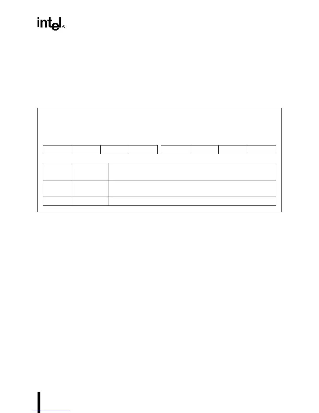
Figure 9-9. Initialization Command Word 2 Register (ICW2)
Initialization Command Word 2
ICW2 (master and slave)
(write only)
Expanded Addr:
ISA Addr:
Reset State:
master slave
F021H F0A1H
0021H 00A1H
XXH XXH
7 0
T7 T6 T5 T4 T3 0 0 0
Bit
Number
Bit
Mnemonic
Function
7–3 T7:3 Base Interrupt Type:
Write the base interrupt vector’s five most-significant bits to these bits.
2–0 T2:0 Clear these bits to guarantee device operation.