A-1
APPENDIX A
SIGNAL DESCRIPTIONS
This appendix provides reference information for the pins and signals of the device, including the
states of certain pins during reset, idle, powerdown, and hold. The information is presented in four
tables:
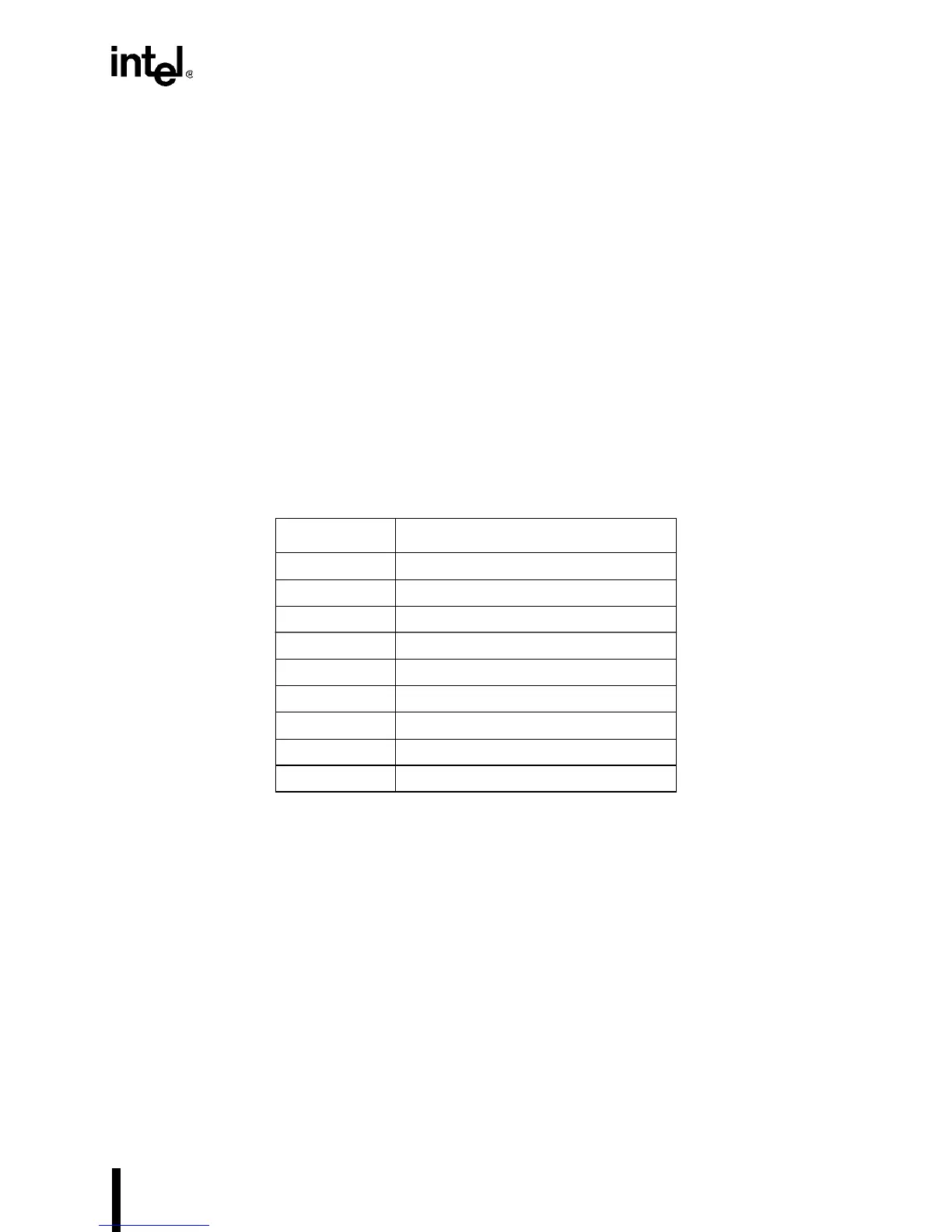
• Table A-1 defines the abbreviations used in Table A-2 to describe the signals.
• Table A-2 describes each signal.
• Table A-3 defines the abbreviations used in Table A-4 to describe the pin states.
• Table A-4 lists the states of output and bidirectional pins after reset and during idle mode,
powerdown, and hold.
Table A-1. Signal Description Abbreviations
Abbreviation Definition
# signal is active low
— not applicable or none
I standard TTL input
O standard CMOS output
OD open-drain output
I/O bidirectional (input and output)
ST Schmitt-trigger input
P power pin
G ground pin

 Loading...


