2-M3
F2880, F3680, RCK72-F36, RCK72R-F36, RCK60-F36, RCK60R-F36, WSM
TRANSMISSION
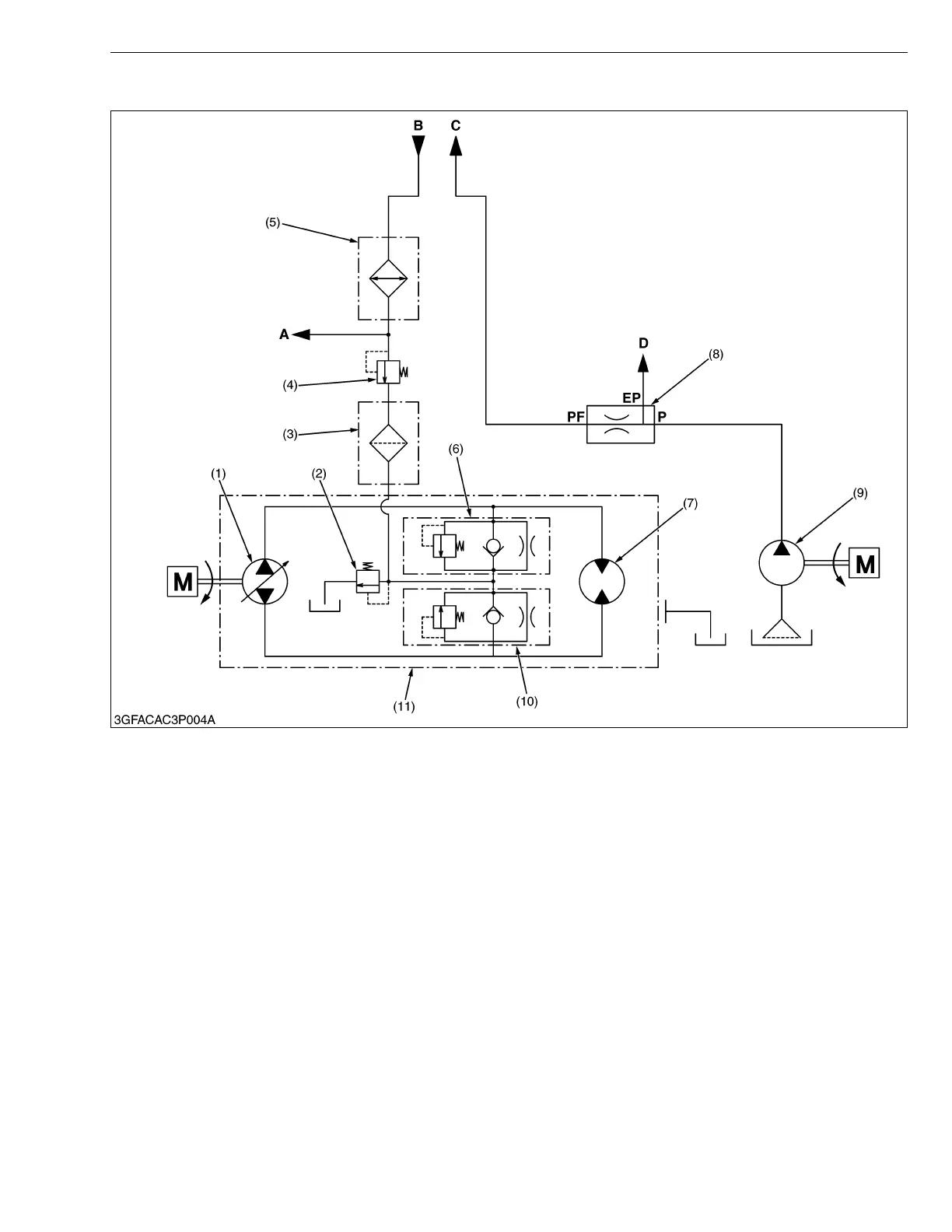
(2) Oil Flow
The closed hydraulic oil loop runs between the pump (1) and motor (7) in the hydrostatic transmission (11).
When the engine is started, the hydraulic pump (9) is rotated to drow oil from the transmission case through the
suction pipe.
The oil is forced out by the hydraulic pump (9) to the power steering controller through the flow priority valve (8).
When the control valve in the power steering controller is at “Neutral” position, the oil is delivered to the oil cooler
(5).
The oil from the oil cooler (5) is delivered to the PTO charge relief valve (4), oil filter cartridge (3) and charge relief
valve (2).
The oil is drained into the transmission case through the hydrostatic transmission housing.
(1) Pump
(2) Charge Relief Valve
(3) Oil Filter Cartridge
(4) PTO Charge Relief Valve
(5) Oil Cooler
(6) Check and High Pressure
Relief Valve
(7) Motor
(8) Flow Priority Valve
(9) Hydraulic Pump
(10) Check and High Pressure
Relief Valve
(11) Hydrostatic Transmission
A : To PTO Control Valve
B : From Power Steering
Controller
C : To Power Steering Controller
D : To Implement Control Valve
EF :EF Port
PF :PF Port
P : P Port
 Loading...