8-M5
F2880, F3680, RCK72-F36, RCK72R-F36, RCK60-F36, RCK60R-F36, WSM
ELECTRICAL SYSTEM
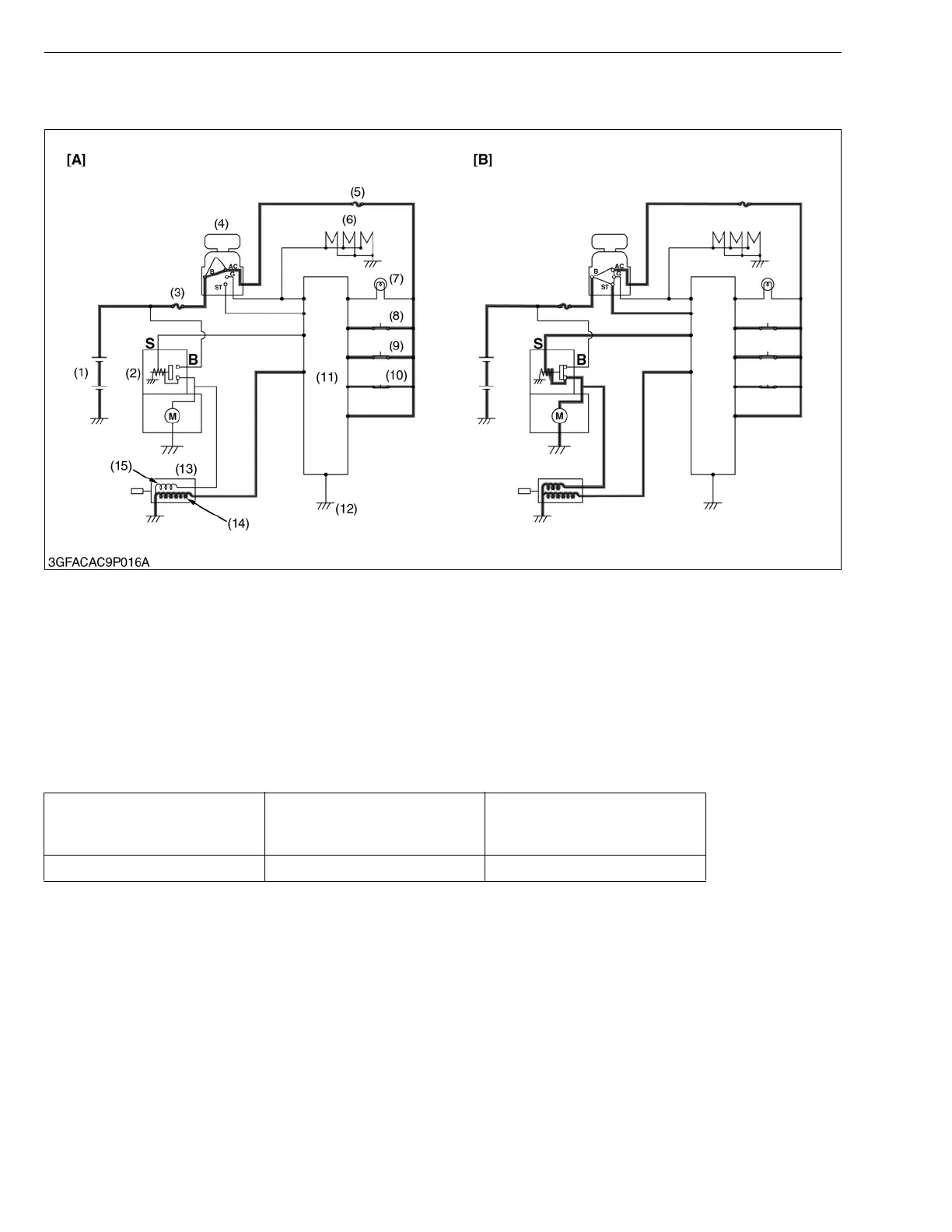
(2) Operation
■ Starting the Engine
When the main switch (4) is turned to the “ON” position (AC terminal) under the following condition, the electrical
current flows to the holding coil (14) of the engine stop solenoid (13). (Figure [A])
When the main switch (4) is turned to the “START” position (ST terminal), the electrical current flows to the starter
(2). Then, the electrical current flows to the pulling-in coil (15) of the engine stop solenoid (13) through the starter (2).
(Figure [B]) The engine can be started.
W1014766
(1) Battery
(2) Starter
(3) Slow Blow Fuse (50A)
(4) Main Switch
(5) Fuse (5A)
(6) Glow Plug
(7) Glow Plug Lamp
(8) Seat Switch
(9) PTO Switch
(10) Brake Switch
(11) Controller
(12) Frame Earth
(13) Engine Stop Solenoid
(14) Holding Coil
(15) Pulling-in Coil
[A] When the main switch is
turned to the “ON” position
(AC terminal)
[B] When the main switch is
turned to the “START”
position (ST terminal)
Seat Switch (8)
(Occupied : ON)
(Vacant : OFF)
PTO Switch (9)
(Disengaged : ON)
(Engaged : OFF)
Brake Switch (10)
(Pedal depressed : ON)
(Pedal free : OFF)
ON ON ON
 Loading...