Parameter setting
With communication module LECOM−A (RS232)
6−11
L
EDB82MV752 EN 5.2
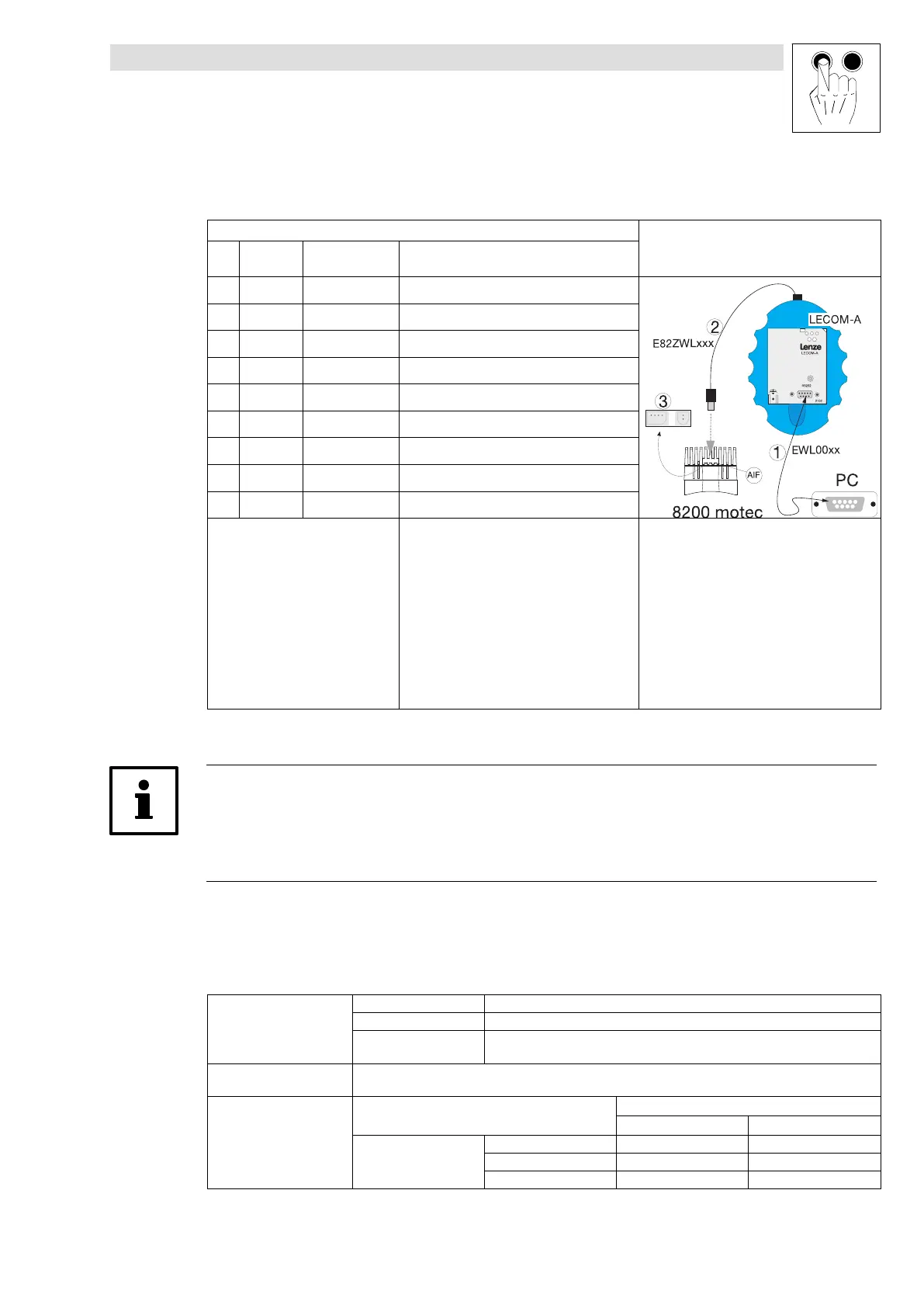
6.3.2 Wiring to a host (PC or PLC)
Pin assignment of 9−pole SubD socket
Installation/commissioning
Pin Designatio
n
Input (E) / output
(A)
Explanation
1 − − not assigned
2 RxD e Data reception" cable
3 TxD a Data transmission" cable
4 DTR a Transmission control
5 GND − Reference potential
6 DSR e not assigned
7 − − not assigned
8 − − not assigned
9 GND Reference potential for T/R (A), T/R (B) and +5 V
= PC system cable
= connecting cable
= plug
The Global Drive Control easy parameterisation
software must be installed on your PC.
1. Connect communication module to the PC via
PC system cable 1.
2. Insert the connecting cable 2 into the
diagnosis terminal.
3. Remove protective cap 3 from the motec
heatsink.
4. Connect connecting cable 2 to the interface
(AIF) of the controller.
When the mains voltage is switched on, the
communication module is ready for operation. You
can communicate with the drive.
Tip!
The controller has a double basic insulation to EN 50178. An additional electrical isolation is
not required.
Use the Lenze accessories listed for wiring.
6.3.2.1 Notes on self−made PC system cables
Specification for RS232
interface cable
Cable type LIYCY 4 x 0.25 mm
2
shielded
Cable resistance 100 /km
Capacitance per unit
length
140 nF/km
Specification for SubD
connector
Use metallic SubD housing only.
Connect the shield on both ends to the housing.
Pin assignment
Must be connected to PC or similar with
at communication module 9−pole SubD socket pin 25−pole SubD socket pin
9−pole SubD plug pin
2 (RxD) 3 (TxD) 2 (TxD)
3 (TxD) 2 (RxD) 3 (RxD)
5 (GND) 5 (GND) 7 (GND)
 Loading...