Installation notes:
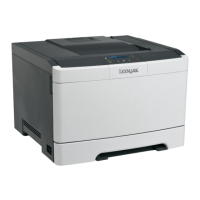
a After routing the thermistor cable through the hole at the rear of the printer, make sure that the sensor is
placed behind the transfer module retract mechanism to avoid interference with the transfer module retract.
b After installing the sensor to the printer, restart the printer to test the cable connections to the sensor. A
128.xx error indicates a bad connection at the sensor.
c Perform the TPS sensor characterization.
Enter the Diagnostics menu, and then navigate to:
Printer Diagnostics > Printer Setup > EP setup > Toner patch sensor adjust > Sensor Gain Characterization
d Perform the TPS sensor calibration.
Enter the Diagnostics menu, and then navigate to:
Printer Diagnostics > Printer Setup > EP setup > Toner patch sensor adjust > Full Calibration
TPS sled removal
Note: This is not a FRU.
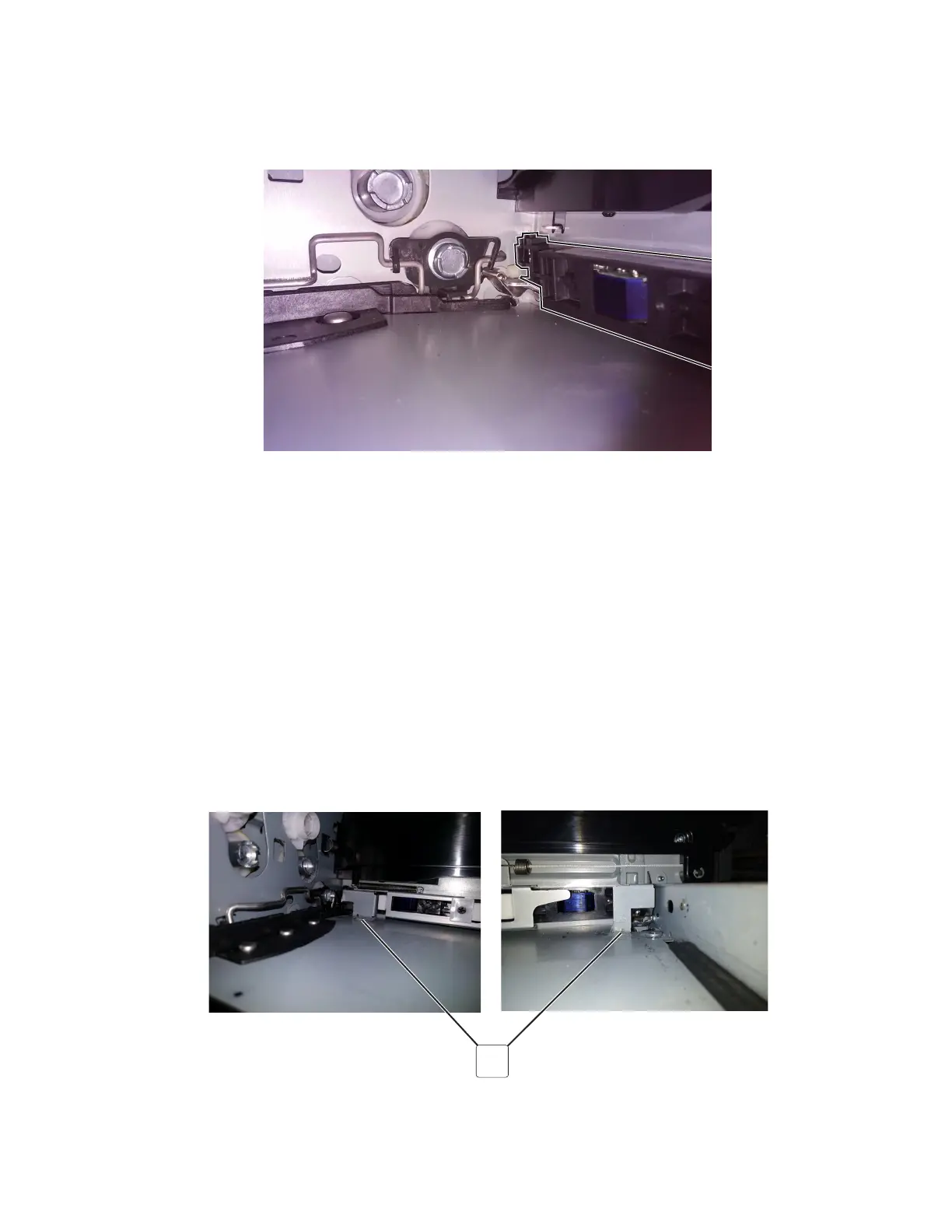
1 Remove the interlocks (A).
A
2 Disconnect the two springs (B) from the TPS sled.
5028
Repair information
327
 Loading...