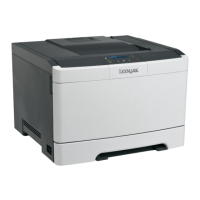
6 Remove the rear left screw (E) from the printhead.
Installation note: When installing the printhead, replace the screws but do not tighten them right away.
After installing the screws, turn the printhead clockwise until it stops before tightening the screws fully.
After performing these steps, you may need to align the printhead if there is skew. You will also need to
perform (TBD).
Developer hold down removal
1 Remove the top cover. See “Top cover removal” on page 268.
2 Remove the controller board shield. See “Controller board shield removal” on page 356.
3 Remove the printhead. See “Printhead removal” on page 361.
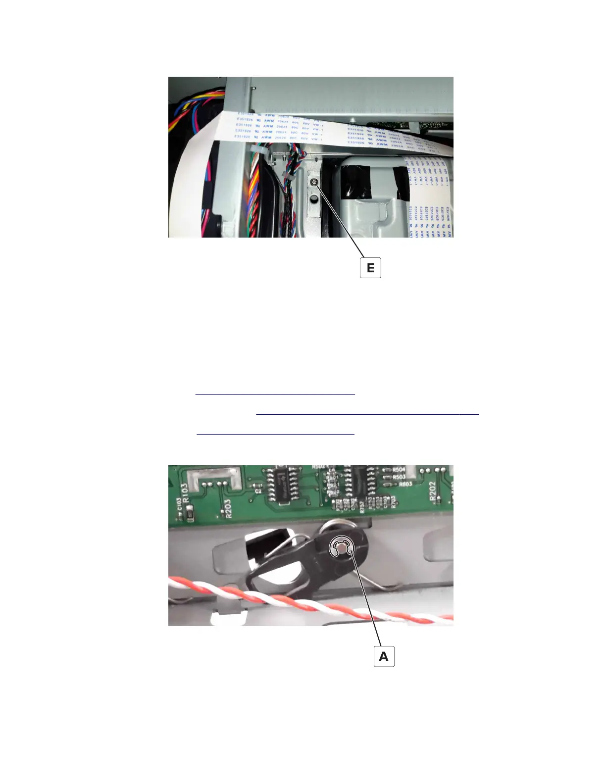
4 Pull the bell crank and spring
o
the mounting pin.
5028
Repair information
363
 Loading...