MMX8x4-HT series – User's Manual 116
Test Pattern
The output ports can send a special image towards the sink devices for testing purposes. The setting is
available on output ports with the below-listed parameters.
ATTENTION! The Mode can be set individually on each port, but the Clock source and the Pattern settings
are common on the O1 and O2, O3 and O4 output ports.
Test pattern generator mode setting
Command and Response#testpattern#nosyncscreen
ç <out><tpg_mode>
æ <out><tpg_mode>
Parameters
Parameter description Parameter values
<tpg_mode> Test pattern generator
mode
0: Disabled - The test pattern is not displayed on the
output.
1: Enabled - The test pattern is displayed on the output.
2: No signal mode - The test pattern is displayed if there is
no signal on the output port.
Example
ç
æ
Clock source – the clock frequency of the test pattern
Command and Response
ç <out><tpg_clocksource>
æ <out><tpg_clocksource>
Parameters
Parameter
description
Parameter values
<tpg_clocksource>
Clock frequency
480: 480p
576: 576p
External clock (from current TMDS source)
Example
ç
æ pw
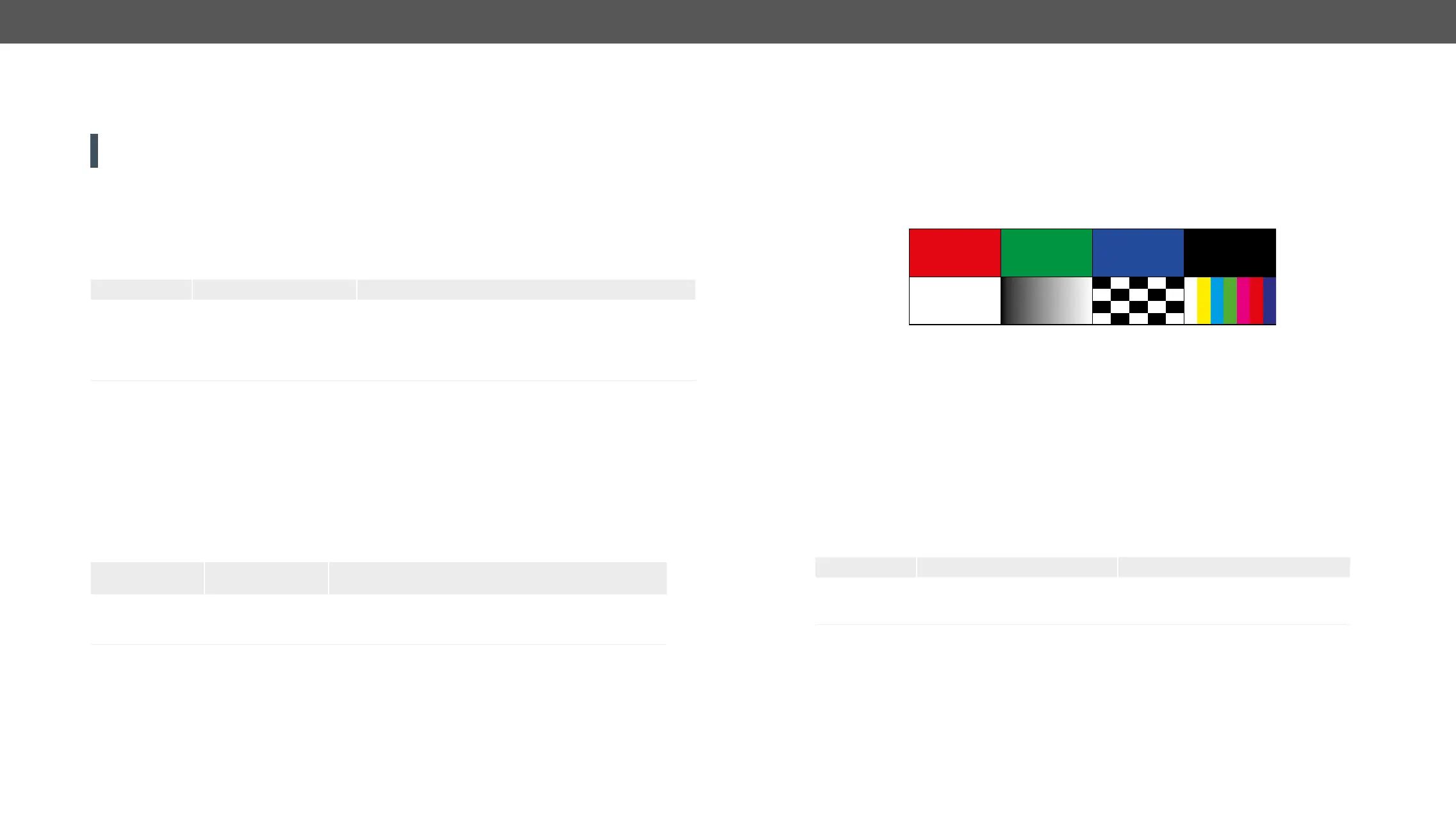
Test pattern
Command and Response
ç <out><pattern>
æ <out><pattern>
Parameters
<pattern>
RED GREEN BLUE BLACK WHITE RAMP CHESS BAR CYCLE
Cycle setting means all the patterns are changed sequentially approx. in every 2 seconds.
Example
ç
æ
EDID Management
It displays the emulated EDID memory place for each input port (I1-I8).
Command and Response
ç
æ <source>:E1;<source>:E2;<...>;<source>:E8
Parameters
Parameter description Parameter values
<source> Source EDID memory place F#: Factory (F1-149)
U#: User (U1- U24* or U1- U27)
D#: Dynamic (D1-D5 or D1-D8*)
* In MMX8x8-HDMI-4K-A model.
Example
ç
æ
All emulated EDID memories (inputs) are listed with the EDID number that is currently emulated on the input
separated by semicolons. Above example shows that F149 EDID (149th Factory EDID) is emulated on I1 (E1) port,
and F47 is emulated on all other input ports.
 Loading...