[ VII Control ]
- 93 -
HWE10060 GB
External water temperature sensor TW-TH16
1. Parts that are required to install an external water
temperature sensor
(1) External water temperature sensor
(2) Wiring to connect the sensor and the unit*
(3) Wiring terminals to connect the wiring to the sensor and
the terminal block on the unit
(Four for M4 screws)*
*Items (1) and (2) are field supplied.
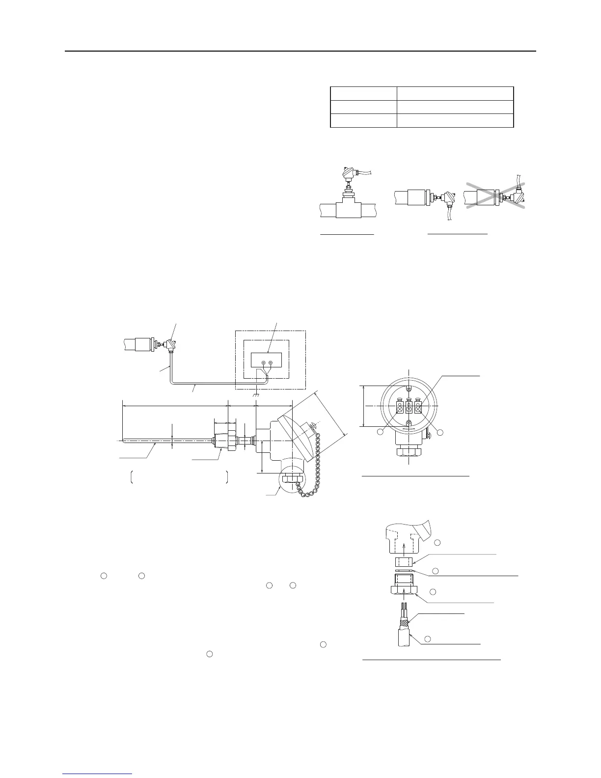
2. Installing the external water temperature sensor
Install the external water temperature sensor where the
water pipes merge or on the load-side tank as shown in
the figure at right.
Install horizontally or vertically on top of the pipe.
When installing horizontally, make sure the wire faces
down.
3. Wiring the external water temperature sensor
Connect the external temperature sensor wiring to the terminal block in the control box on the unit as shown in the
figure below.
Wire specifications
Wire size 2-core cable Min. 1.25 mm
2
Type CVVS or CPEVS
Maximum length 20 m
Note
Sensor wire
External water temperature sensor
Control box
12-pin terminal block in the control box on the unit
Unit
50
48
T2T1
A
· B-constant: 3460K
R 1/2
Sensor
Sensor properties
· Resistance: R=15KΩ±3% (0 °C)
Terminal block for connection to the sensor
M4 screws × 3
Terminal screws
A
BB
(Note)
Run the sensor wiring at least 5 cm away from any wire that
carries a voltage of 100 V or more, and do not put the sensor
wiring in the same conduit tube with it.
ø
78
5442157
20
12
ø10
Ø6
Connect the sensor wiring to terminals T1 and T2 of the 12-pin terminal
block in the control box on the unit.
Connect the shield to the earth terminal.
Cut the shield wire. Do not connect it to the terminal. (Connect the shield on the
unit side to the ground terminal.)
Detailed view of the area labeled "A" in the figure above
Shield (to be cut)
Field-supplied wire
Water-sealing rubber
(Internal diameter ø11)
Washer (Internal diameter ø12)
Tightening screw
(Internal diameter ø15)
1
2
4
3
5
6
Thread the wire to the external water temperature sensor through parts
through as shown in the figure at right. Attach M4 terminals
(field-supplied) to the wires, and connect them to and (terminals A and B).
24
5
6
After the wire is connected, securely tighten the tightening screw , and then
caulk the gap between the wire and the tightening screw to keep water
from entering.
4
1
 Loading...