[ IX Troubleshooting ]
- 122 -
HWE10060 GB
[3] Troubleshooting Principal Parts
High-Pressure Sensor
-1- High-Pressure Sensor (63HS)
1. Compare the pressure that is detected by the high pressure sensor, and the high-pressure gauge pressure to check
for failure.
Error history, temperature and pressure readings of the sensor, and LEV opening
(1) While the sensor is stopped, compare the gauge pressure and the pressure displayed on self-diagnosis LED1.
1) When the gauge pressure is between 0 and 0.098MPa, internal pressure is caused due to gas leak.
2) When the pressure displayed on self-diagnosis LED1 is between 0 and 0.098MPa, the connector may be defective or be dis-
connected. Check the connector and go to (4).
3) When the pressure displayed on self-diagnosis LED1 exceeds 3.85MPa, go to (3).
4) If other than 1), 2) or 3), compare the pressures while the sensor is running. Go to (2).
(2) Compare the gauge pressure and the pressure displayed on self-diagnosis LED1 while the sensor is running. (Com-
pare them by MPa unit.)
1) When the difference between both pressures is within 0.098MPa, both the high pressure sensor and the control board are
normal.
2) When the difference between both pressures exceeds 0.098MPa, the high pressure sensor has a problem. (performance de-
terioration)
3) When the pressure displayed on self-diagnosis LED1 does not change, the high pressure sensor has a problem.
(3) Remove the high pressure sensor from the control board to check the pressure on the self-diagnosis LED1.
1) When the pressure displayed on self-diagnosis LED1 is between 0 and 0.098MPa , the high pressure sensor has a problem.
2) When the pressure displayed on self-diagnosis LED1 is approximately 3.85MPa, the control board has a problem.
(4) Remove the high pressure sensor from the control board, and short-circuit between the No.2 and 3 connectors
(63HS:CN63HS) to check the pressure with self-diagnosis LED1.
1) When the pressure displayed on the self-diagnosis LED1 exceeds 3.85MPa, the high pressure sensor has a problem.
2) If other than 1), the control board has a problem.
2. Pressure sensor configuration
The high pressure sensor consists of the circuit shown in the figure below. If DC 5V is applied between the red and the black
wires, voltage corresponding to the pressure between the white and the black wires will be output, and the value of this voltage
will be converted by the microcomputer. The output voltage is 0.071V per 0.098MPa.
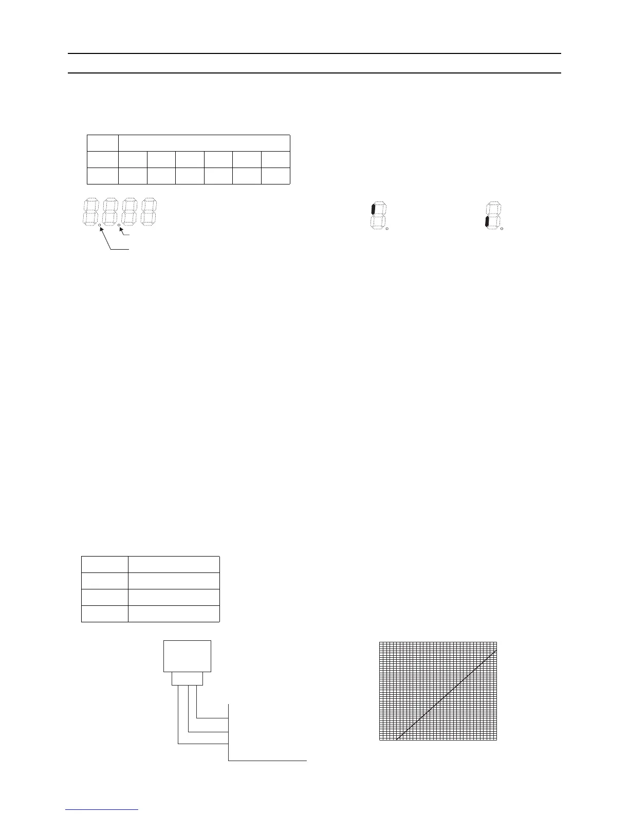
SW2 SW3 High pressure and low pressure will appear alternately on the 7-seg-
ment LED at P-second intervals (Default: 3 seconds). See below for
how they are displayed.
10 5 6 7 8 9 10
OFF OFF OFF OFF OFF OFF OFF
Control board side
Vcc Pin 3
Vout Pin 2
GND Pin 1
 Loading...