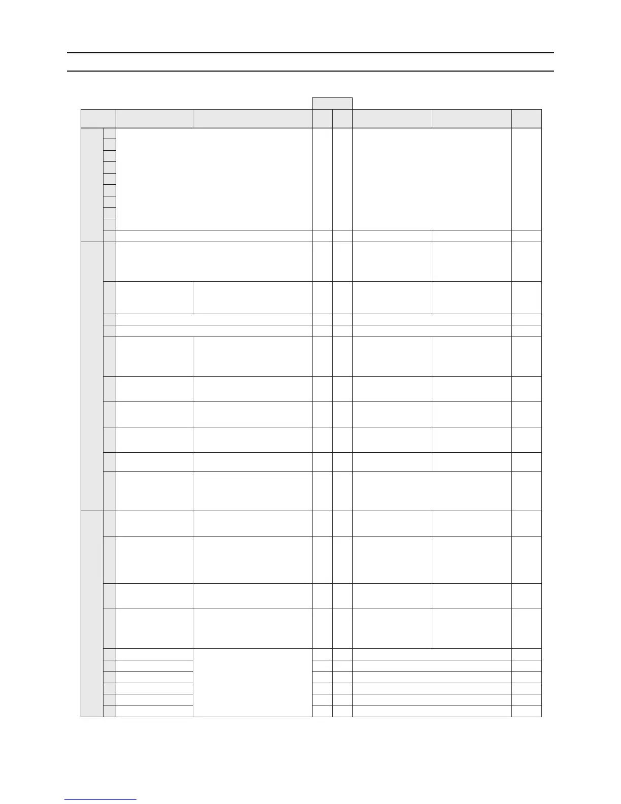
"-" in the table indicates that the function in the corresponding row will be disabled regardless of the actual switch setting.
The factory setting for these items is OFF.
Refer to page 23 for (5)Resetting the system.
Factory setting
SW Function Usage
MAIN
circuit
SUB
circuit
OFF setting ON setting
Setting
timing
SW1
1
Model setting
Depends
on the unit
teser a tA.si ti sa gnittes eht evaeL-
2
3
4
5
6
7
8
9
teser a tA.si ti sa gnittes eht evaeL-FFOgnittes ledoM01
SW2
-FFOgnittes noitcetorp pu-ezeerF1
Starts the pump when both
the outside and water
temperatures drop to
prevent water pipe freeze
up.
At a reset
2
Scheduled operation
display
Turns on and off the remote display during
scheduled operation.
OFF -
Turns off the operation
display during the period in
which the unit is scheduled
to be stopped.
Leaves the operation
display on during the period
in which the unit is
scheduled to be stopped.
At a reset
teser a tA.si ti sa gnittes eht evaeL-FFOgnittes ledoM3
teser a tA.si ti sa gnittes eht evaeLFFOgnittes ledoM4
5
Recovery conditions after
forced stoppage
Selects what the operation restoration
condition will be based on after the unit
was forced to stop based on the external
thermistor reading (water outlet
temperature).
OFF - External thermistor Built-in thermistor At a reset
6
Power supply option to the
communication circuit
Switches between supplying or not
supplying power to the communication
circuit.
-ON
Supplies power to the
communication circuit.
Does not supply power to
the communication circuit.
Any time
7
Remote water-temperature
setting
Allows or disallows the water temperature
to be set using analog signals from a
remote location.
OFF -
Disallows the water
temperature to be set using
external analog signals.
Allows the water
temperature to be set using
external analog signals.
At a reset
8
Water-temperature control
option
Selects either the external water
temperature sensor or the built-in sensor
to be used to control water temperature.
OFF - Built-in sensor on the unit
External water temperature
sensor
At a reset
9 Individual/Multiple system
Selects between individual and Multiple
system
OFF - Individual system Multiple system At a reset
10 Display mode switch 7
This switch is used in combination with dip
switches SW3-5 through 3-10 and push
switches SWP 1, 2, and 3 to configure or
view the settings when performing a test
run or changing the system configuration.
OFF Changes the 7-segment LED display mode. Any time
SW3
1 Remote reset
Enables or disables the error to be reset
from a remote location.
ON -
Disables the error to be
reset from a remote
location.
Enables the error to be
reset from a remote
location.
At a reset
2
Auto restart after power
failure
Enables or disables the automatic
restoration of operation after power failure
(in the same mode as the unit was in
before a power failure).
ON -
An alarm will be issued
when power is restored
after a power outage.
The alarm will be reset
when the power is turned off
and then turned back on.
Automatically restores
operation after power
failure.
At a reset
3 Water-temperature control
Switches between inlet-water-
temperature-based control and outlet-
water-temperature-based control.
OFF -
Outlet-water-temperature-
based control
Inlet-water-temperature-
based control
At a reset
4
Pump-thermistor interlock
setting
Interlocks or does not interlock the
operation of the pump with the external
thermistor.
(Effective only when SW2-8 is set to ON.)
OFF -
The pump turns on when
the operation switch is
turned on regardless of the
Thermo-ON/Thermo-OFF
status.
Interlocks the operation of
the pump with the Thermo-
ON/Thermo-OFF status.
At a reset
5 Display mode switch 1
These switches are used in combination
with dip switches SW2-5 and push
switches SWP 1, 2, and 3 to configure or
view the settings when performing a test
run or changing the system configuration.
OFF Changes the 7-segment LED display mode. Any time
emit ynA.edom yalpsid DEL tnemges-7 eht segnahCFFO2 hctiws edom yalpsiD6
emit ynA.edom yalpsid DEL tnemges-7 eht segnahC FFO3 hctiws edom yalpsiD7
emit ynA.edom yalpsid DEL tnemges-7 eht segnahC FFO4 hctiws edom yalpsiD8
emit ynA.edom yalpsid DEL tnemges-7 eht segnahC FFO5 hctiws edom yalpsiD9
emit ynA.edom yalpsid DEL tnemges-7 eht segnahC FFO6 hctiws edom yalpsiD01
OFF
OFF
OFF
OFF
OFF
OFF
OFF
OFF
Same as when set to OFF
 Loading...