EasyManuals Logo

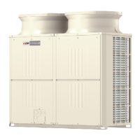
Mitsubishi Electric CAHV-P500YA-HPB Service Handbook

Mitsubishi Electric CAHV-P500YA-HPB
160 pages
To Next Page IconTo Next Page
To Previous Page IconTo Previous Page
Page #38 background imageLoading...
Page #38 background image
[ III Unit Components ]
- 31 -
HWE10060 GB
III Unit Components
[1] Unit Components and Refrigerant Circuit
1. Unit Components
Frame assy L
(1) Front view
(2) Rear view
(3) Fan
Frame assy R
Pillar LF
Panel
assy F
Panel 1
Panel assy FBL
Cover piping
Panel M
Panel B
Frame assy B
Fin guard B
Pillar B
Guard fixed plate Guard fixed plate
Pillar B (R)Pillar B (L)
Panel
assy FB
Panel assy FU
Pillar F(L)
Pillar LF
Panel TOP
Pillar RF
Pillar F(R)
Fan guard
Fin guard LR
Frame
assy MB
Frame
assy MU
Pillar RF
Frame F.
Frame FB
Attachment leg
Base fan
Upset screw
Box nut
Fan
Motor
H screw.
WFT screw

Table of Contents

Other manuals for Mitsubishi Electric CAHV-P500YA-HPB

Questions and Answers:

Question and Answer IconNeed help?

Do you have a question about the Mitsubishi Electric CAHV-P500YA-HPB and is the answer not in the manual?

Mitsubishi Electric CAHV-P500YA-HPB Specifications

General IconGeneral
BrandMitsubishi Electric
ModelCAHV-P500YA-HPB
CategoryHeat Pump
LanguageEnglish

Related product manuals