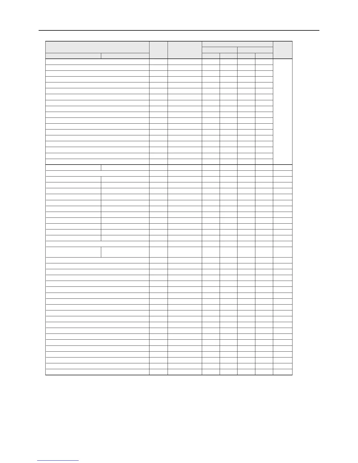
Sensors and item code list
Item
Item
code
LED display
Unit and circuit type
NotesMain unit Sub unit
MAIN circuit SUB circuit
MAIN circuit SUB circuit MAIN circuit SUB circuit
Error history 1 1 Error Code ○ ○ ○ ○
(Note1)
Error history 1 details (Inverter error) 2 Error Code ○ ○ ○ ○
Error history 1/Occurrence time 3 Time ○ ○ ○ ○
Error history 2 4 Error Code ○ ○ ○ ○
Error history 2 details (Inverter error) 5 Error Code ○ ○ ○ ○
Error history 2/Occurrence time 6 Time ○ ○ ○ ○
Error history 3 7 Error Code ○ ○ ○ ○
Error history 3 details (Inverter error) 8 Error Code ○ ○ ○ ○
Error history 3/Occurrence time 9 Time ○ ○ ○ ○
Error history 4 10 Error Code ○ ○ ○ ○
Error history 4 details (Inverter error) 11 Error Code ○ ○ ○ ○
Error history 4/Occurrence time 12 Time ○ ○ ○ ○
Error history 5 13 Error Code ○ ○ ○ ○
Error history 5 details (Inverter error) 14 Error Code ○ ○ ○ ○
Error history 5/Occurrence time 15 Time ○ ○ ○ ○
Error history 6 16 Error Code ○ ○ ○ ○
Error history 6 details (Inverter error) 17 Error Code ○ ○ ○ ○
Error history 6/Occurrence time 18 Time ○ ○ ○ ○
Inlet water temp (Twi )
Inlet water temp 2 TH12 c01 First decimal place ○ ○ ○ ○ (Note2)
Outlet water temperature (Two) c02 First decimal place ○ ○ ○ ○ (Note2)
Discharge refrigerant 1 TH1 Discharge refrigerant 2 TH5 c03 First decimal place ○ ○ ○ ○ (Note2)
Suction refrigerant 1 TH2 Suction refrigerant 2 TH6 c04 First decimal place ○ ○ ○ ○ (Note2)
Shell temperature 1 TH3 Shell temperature 2 TH7 c05 First decimal place ○ ○ ○ ○ (Note2)
Air-side heat exchanger inlet 1 TH4
Air-side heat exchanger inlet 2 TH8
c06 First decimal place ○ ○ ○ ○ (Note2)
Outside temperature TH9 Outside temperature TH9 c07 First decimal place ○ ○ ○ ○ (Note2)
Inlet water temperature 1 TH10
Inlet water temperature 2 TH12
c08 First decimal place ○ ○ ○ ○ (Note2)
Outlet water temperature 1 TH11
Outlet water temperature 2 TH13
c09 First decimal place ○ ○ ○ ○ (Note2)
Representative water temperature 1 TH14
- c10 First decimal place ○ Fixed to 0 Fixed to 0 Fixed to 0 (Note2)
Representative water temperature 2 TH15
- c11 First decimal place
Second decimal place
Second decimal place
○ Fixed to 0 Fixed to 0 Fixed to 0 (Note2)
High pressure 1 HP1 High pressure 2 HP2 c12 ○ ○ ○ ○ (Note3)
Low pressure 1 LP1 Low pressure 2 LP2 c13 ○ ○ ○ ○ (Note3)
Heatsink temperature(THHS) c14 First decimal place ○ ○ ○ ○ (Note2)
- c15 First decimal place (Note13) Fixed to 0 Fixed to 0 Fixed to 0 (Note4)
I u(U-phase current)(Compressor) c16 First decimal place ○ ○ ○ ○ (Note4)
I w(W-phase current)(Compressor) c17 First decimal place ○ ○ ○ ○ (Note4)
I dc(Bus current)(Compressor) c18 First decimal place ○ ○ ○ ○ (Note4)
Vdc(Bus voltage)(Compressor) c19 Integer ○ ○ ○ ○ (Note5)
I u(U-phase current)(Fan) c20 First decimal place ○ ○ ○ ○ (Note4)
I w(W-phase current)(Fan) c21 First decimal place ○ ○ ○ ○ (Note4)
I dc(Bus current)(Fan) c22 First decimal place ○ ○ ○ ○ (Note4)
V dc(Bus voltage)(Fan) c23 Integer ○ ○ ○ ○ (Note5)
Suction SH (target) c24 First decimal place ○ ○ ○ ○ (Note6)
Compressor frequency (actual frequency) c25 Integer ○ ○ ○ ○ (Note7)
Suction SH c26 First decimal place ○ ○ ○ ○ (Note8)
Shell bottom SH c27 First decimal place ○ ○ ○ ○ (Note9)
Operating frequency of the fan (actual frequency) c28 Integer ○ ○ ○ ○ (Note10)
Opening of the LEV on the main circuit c29 Integer ○ ○ ○ ○ (Note11)
Injection LEV opening c30 Integer ○ ○ ○ ○ (Note11)
(Note14)
(Note14)
Discharge SH (target) c31 First decimal place ○ ○ ○ ○ (Note6)
Discharge SH c32 First decimal place ○ ○ ○ ○ (Note12)
Target water temperature c33 First decimal place ○ ○ ○ ○ (Note6)
c35 First decimal place (Note13) Fixed to 0 Fixed to 0 Fixed to 0
c36 First decimal place (Note13) Fixed to 0 Fixed to 0 Fixed to 0
(Note1) Refer to the section “1. Checking the error history” for further information. (Page 105)
(Note2) Codes c01 through C11 and c14 indicate temperature sensors.
(Note3) Codes c12 and c13 indicate pressure sensors.
(Note4) Codes c15 through c18 and c20 through 22 indicate current sensors.
(Note5) Codes c19 and c23 indicate voltage sensors.
(Note6) Codes c24, c31, and c33 indicate target values.
(Note7) Code c25 indicates compressor's operating frequency.
(Note8) Code c26 indicates superheat that was calculated based on the low pressure and suction refrigerant temperature.
(Note9) Code c27 indicates superheat that was calculated based on the low pressure and shell temperature.
(Note10) Code c28 indicates the operating frequency of the fan.
(Note11) Codes c29 and c30 indicate the degree of LEV opening.
(Note12) Code c32 indicates superheat that was calculated based on high pressure and discharge refrigerant temperature.
(Note13) When the input type is selected. When the input type is not selected = 0.
(Note14) c35 and c36 show the external analog input values (water temperature settings)
Water temperature setting using an external
analog input (4-20 mA Current input)
Water temperature setting using an external analog input (0-10 V or 2-10 V Voltage input)
Water temperature setting using an external analog input (1-5 V Voltage input)
 Loading...