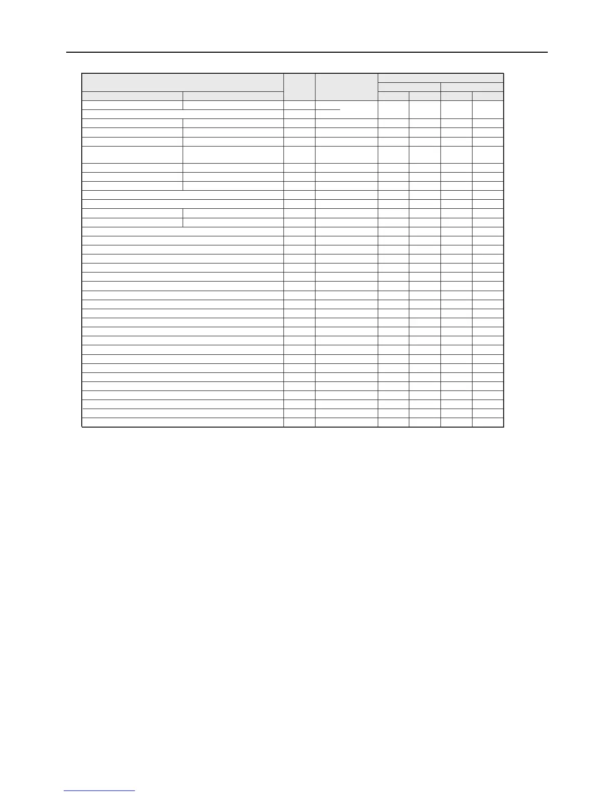
(Note1) Each circuit board displays error data of its own unit and not other units.
(Note2) "Before error" is defined as the period between 19 minutes before the occurrence of an error up to immediately before the occurrence of the error.
(Note3) When the input type is selected. When the input type is not selected = 0
Time of data storage before error
Item
Item
code
LED display
Unit and circuit type
Main unit Sub unit
MAIN circuit SUB circuit
MAIN circuit SUB circuit MAIN circuit SUB circuit
Inlet water temp (Twi )
Inlet water temp 2 TH12 c01 First decimal place ○ ○ ○ ○
Outlet water temperature (Two) c02 First decimal place ○ ○ ○ ○
Discharge refrigerant temperature 1 TH1 Discharge refrigerant temperature 2 TH5
c03 First decimal place ○ ○ ○ ○
Suction refrigerant temperature 1 TH2 Suction refrigerant temperature 2 TH6
c04 First decimal place ○ ○ ○ ○
Shell temperature 1 TH3 Shell temperature 2 TH7 c05 First decimal place ○ ○ ○ ○
Air-side heat exchanger inlet
refrigerant temperature
1 TH4
Air-side heat exchanger inlet
refrigerant temperature
2 TH8
c06 First decimal place ○ ○ ○ ○
Outside temperature TH9 Outside temperature TH9 c07 First decimal place ○ ○ ○ ○
Inlet water temperature 1 TH10 Inlet water temperature 2 TH12 c08 First decimal place ○ ○ ○ ○
Outlet water temperature 1 TH11 Outlet water temperature 2 TH13 c09 First decimal place ○ ○ ○ ○
Representative water temperature 1 TH14 c10 First decimal place ○ Fixed to 0 Fixed to 0 Fixed to 0
Representative water temperature 2 TH15 c11 First decimal place
Second decimal place
Second decimal place
○ Fixed to 0 Fixed to 0 Fixed to 0
High pressure 1 HP1 High pressure 2 HP2 c12 ○ ○ ○ ○
Low pressure 1 LP1 Low pressure 2 LP2 c13 ○ ○ ○ ○
Heatsink temperature(THHS) c14 First decimal place ○ ○ ○ ○
c15 First decimal place (Note3) Fixed to 0 Fixed to 0 Fixed to 0
I u(U-phase current)(Compressor) c16 First decimal place ○ ○ ○ ○
I w(W-phase current)(Compressor) c17 First decimal place ○ ○ ○ ○
I dc(Bus current)(Compressor) c18 First decimal place ○ ○ ○ ○
V dc(Bus voltage)(Compressor) c19 Integer ○ ○ ○ ○
I u(U-phase current)(Fan) c20 First decimal place ○ ○ ○ ○
I w(W-phase current)(Fan) c21 First decimal place ○ ○ ○ ○
I dc(Bus current)(Fan) c22 First decimal place ○ ○ ○ ○
V dc(Bus voltage)(Fan) c23 Integer ○ ○ ○ ○
Suction SH (target) c24 First decimal place ○ ○ ○ ○
Compressor frequency (actual frequency) c25 Integer ○ ○ ○ ○
Suction SH c26 First decimal place ○ ○ ○ ○
Shell bottom SH c27 First decimal place ○ ○ ○ ○
Operating frequency of the fan (actual frequency) c28 Integer ○ ○ ○ ○
Opening of the LEV on the main circuit c29 Integer ○ ○ ○ ○
Injection LEV opening c30 Integer ○ ○ ○ ○
Discharge SH (target) c31 First decimal place ○ ○ ○ ○
Discharge SH c32 First decimal place ○ ○ ○ ○
Target water temperature c33 First decimal place ○ ○ ○ ○
c35 First decimal place (Note3) Fixed to 0 Fixed to 0 Fixed to 0
c36 First decimal place (Note3) Fixed to 0 Fixed to 0 Fixed to 0
Water temperature setting using an external analog input (4-20 mA Current input)
Water temperature setting using an external analog input (0-10 V or 2-10 V Voltage input)
Water temperature setting using an external analog input (1-5 V Voltage input)
 Loading...