PARAMETERS
134
Pr. 73 "0-5V/0-10V selection"
Pr. 79 "operation mode selection"
Pr. 180 to Pr. 183 (input
terminal function selection)
Pr. 191 to Pr. 192 (output
terminal function selection)
Pr. 902 to Pr. 905 (frequency
setting voltage (current)
biases and
gains)
Related parameters
4.2.37 PID control (Pr. 128 to Pr. 134)
Pr. 128 "PID action selection"
Pr. 129 "PID proportional band"
Pr. 130 "PID integral time"
Pr. 131 "upper limit"
Pr. 132 "lower limit"
Pr. 133 "PID action set point for PU operation"
Pr. 134 "PID differential time"
The inverter can be used to exercise process control, e.g. flow rate, air volume or
pressure.
!
!!
!
The voltage input signal (0 to
±
5V or 0 to
±
10V) or Pr. 133 setting is used as a set
point and the 4 to 20mA DC current input signal used as a feedback value to
constitute a feedback system for PID control.
Parameter
Number
Factory
Setting
Setting Range Remarks
128 0 0, 20, 21
129 100% 0.1 to 1000%, 9999 9999: No proportional control
130 1s 0.1 to 3600s, 9999 9999: No integral control
131 9999 0 to 100%, 9999 9999: Function invalid
132 9999 0 to 100%, 9999 9999: Function invalid
133 0% 0 to 100%
134 9999 0.01 to 10.00s, 9999 9999: No differential control
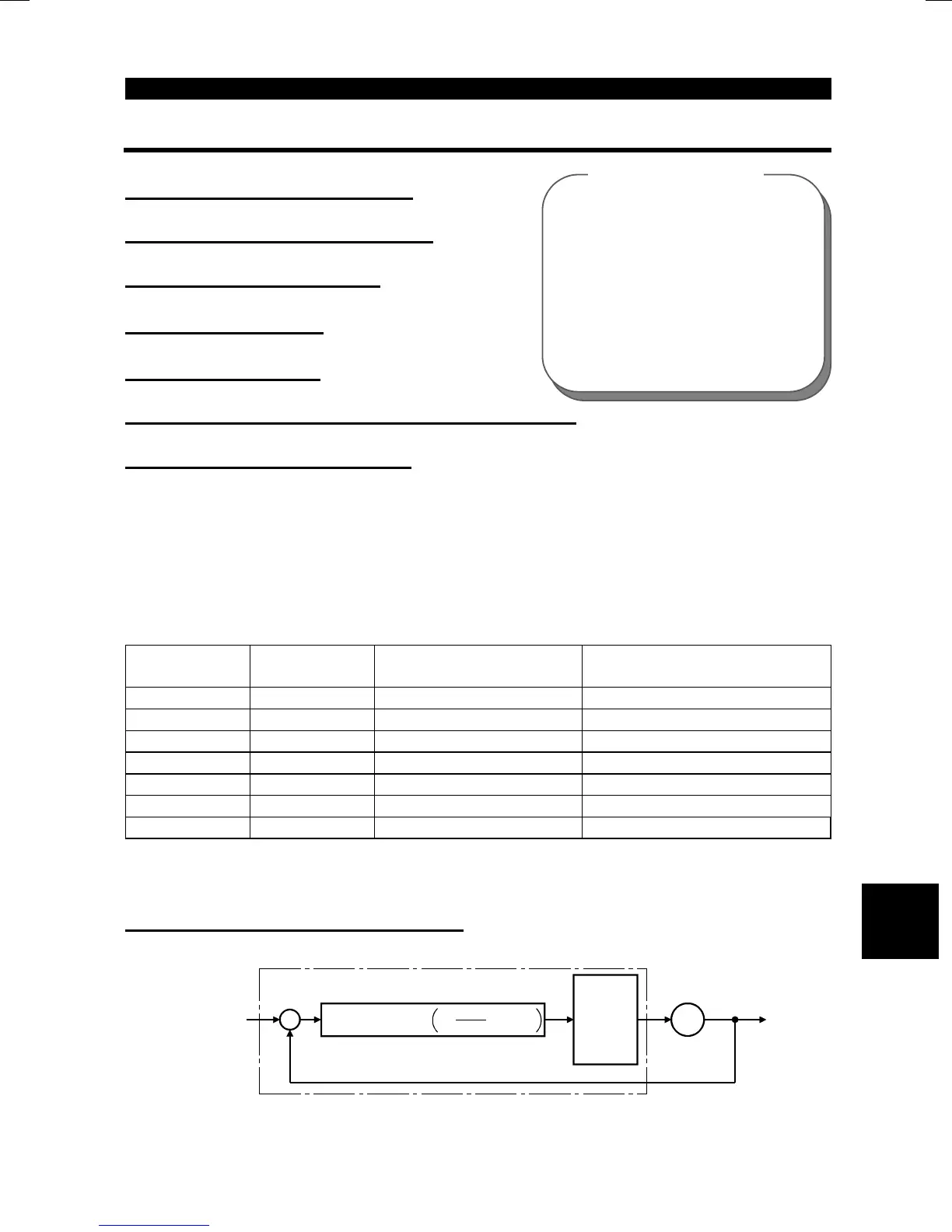
<Setting>
(
1
)
Basic PID control configuration
+
-
(x)
(y)
Deviation
Process value
(fi)
Manipulated variable
Motor
IM
y
Set point
(U)
Ti
×
S
1
Kp
+ +
PID operation
Td
×
S
Drive
circuit
Kp : Proportional constant
Ti : Integral time
S : Operator
Td : Differential time
1
Inverter
4

 Loading...


