2.2 Wiring
INSTALLATION AND WIRING
14
2.2 Wiring
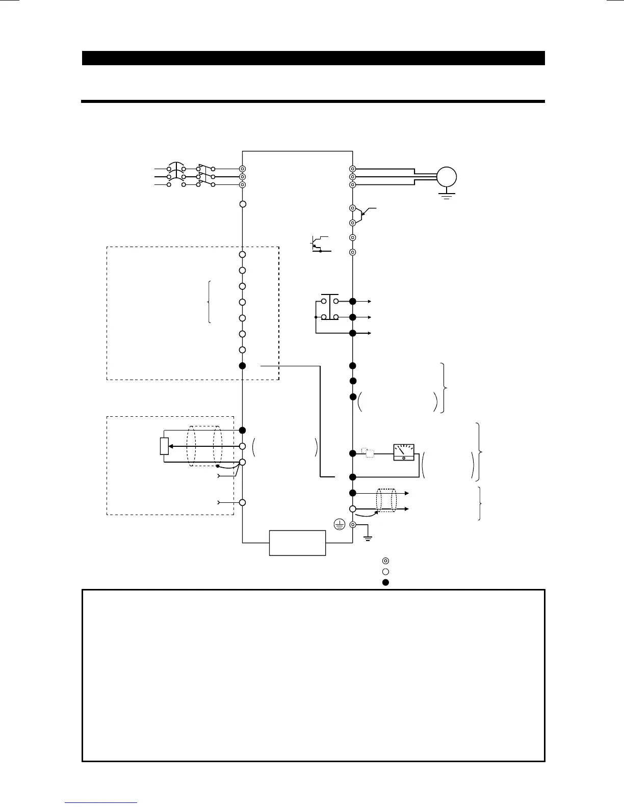
2.2.1 Terminal connection diagram
"
""
"
3-phase 200V power input
"
""
"
3-phase 400V power input
3-phase
AC power
supply
NFB
R(L
1
)
S(L
2
)
T(L
3
)
PC
24VDC power output and
external transistor common
STF
STR
RH
RM
RL
MRS
RES
SD
Forward rotation start
Middle
High
Low
Output stop
Reset
Frequency setting signals (analog)
10(+5V)
2
2
3
1
4 to 20mADC(+)
4(4 to 20mADC)
1/2W1k
Ω
RUN
FU
SE
Running
Frequency detection
FM
SD
Control input signals
(no voltage input allowed)
Jumper
Remove this jumper when
using the optional power-factor
improving DC reactor.
Brake resistor connection
Motor
IM
Ground
Alarm
output
A
B
C
U
V
W
P1
(+)P
PR
(-)N
Meter
(e.g. frequency meter)
+
Main circuit terminal
Control circuit input terminal
Control circuit output terminal
Ground
0 to 5VDC
0 to 10VDC
Selected
Multi-speed selection
Open
collector outputs
Moving-coil
type1mA
full-scale
Contact input common
5(Common)
Open collector
output common)
(Note 1)
Frequency
setting
potentiometer
Current input(-)
PU connector
(RS-485)
Note 2
Reverse rotation start
-
Note 4
Note 4
Note 5
Note 3
Note 3
MC
AM
5
(+)
(
−
)
Analog signal
output
(0 to 10VDC)
For 400V
class
inverter
For 200V
and100V
class
inverters
Calibration
resistor (Note 6)
Note:1. If the potentiometer is to be operated often, use a 2W1k
Ω
potentiometer.
2. 0.1K and 0.2K do not contain a transistor.
3. Terminals SD and SE are isolated.
4. Terminals SD and 5 are common terminals. Do not earth them to the
round. Terminals SD and 5 are not isolated.
Those of the 400V class are
isolated.)
5. When terminals PC-SD are used as a 24VDC
ower su
l
, be careful not
to short these terminals. If they are shorted, the inverter will be damaged.
6. Not needed when the control panel (FR-PA-02-
02
) or parameter unit (FR-
PU04
is used for calibration. Used when calibration must be made near the
fre
uenc
meter for such a reason as a remote fre
uenc
meter. However,
the fre
uenc
meter needle ma
not deflect to full-scale if the calibration
resistor is connected. In this case, use this resistor and the control
anel or
parameter unit together.

 Loading...


