INSTALLATION AND WIRING
22
(
4
)
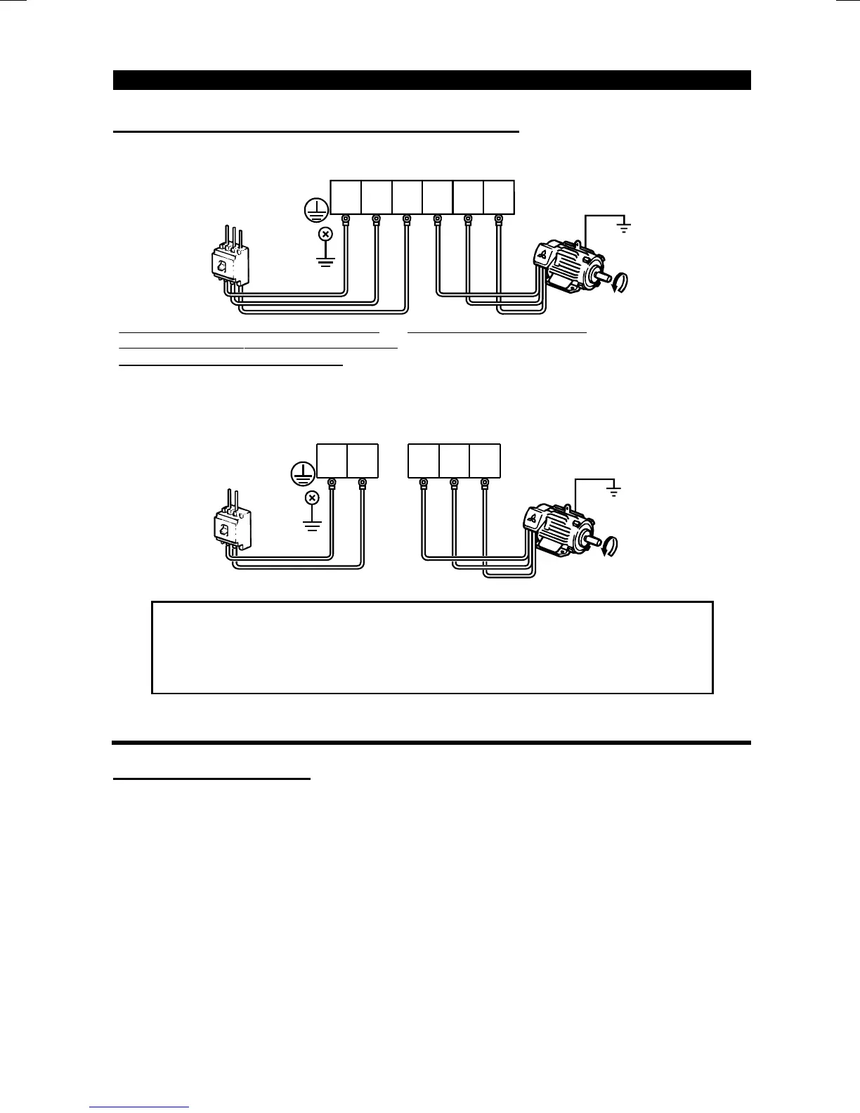
Connection of the power supply and motor
"
""
" Three-phase power input
Ground
Ground
terminal
Three-phase
power supply 200V
Three-phase
power supply 400V
R
(L
1
)
S
(L
2
)
T
(L
3
)
R
(L
1
)
S
(L
2
)
T
(L
3
)
No-fuse
breaker
he power suppl
cables must be connected
o R, S, T
L , L , L ). If they are connected to
U, V, W, the inverter will be damaged. (Phase
equence need not be matched.)
Ground
UVW
U
V
W
Motor
Connect the motor to U, V, W.
In the above
connection, turning on the forward rotation switch (signal)
rotates the motor in the counterclockwise
arrow
direction
when viewed from the load shaft.
1 2 3
"
""
" Single-phase power input
R
(L
1
)
S
(L
2
)
UVW
Ground
Ground
terminal
Ground
Motor
No-fuse
breaker
R
(L
1
)
S
(L
2
)
UVW
Single-phase power
supply 100V
Note:1. To ensure safety, connect the power input to the inverter via a
magnetic contactor and earth leakage circuit breaker or no-fuse
breaker, and use the magnetic contactor to switch power on-off.
2. The output is three-phase 200V.
2.2.3 Wiring of the control circuit
(
1
)
Wiring instructions
1) Terminals SD, SE and 5 are common to the I/O signals. These common terminals
must not be earthed to the ground.
Terminals SD and 5 are not isolated. (Those of the 400V class are isolated.)
2) Use shielded or twisted cables for connection to the control circuit terminals and run
them away from the main and power circuits (including the 200V relay sequence
circuit).
3) The frequency input signals to the control circuit are micro currents. When contacts
are required, use two or more parallel micro signal contacts or a twin contact to
prevent a contact fault.
4) It is recommended to use the cables of 0.3mm
2
to 0.75mm
2
gauge for connection to
the control circuit terminals.
5) When bar terminals and solid wires are used for wiring, their diameters should be
0.9mm (0.04 inches) maximum If they are larger, the screw threads may be
damaged during tightening.

 Loading...


