OUTLINE
3
1.2 Basic Configuration
1.2 Basic Configuration
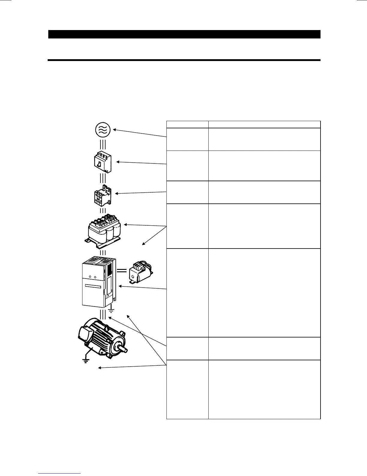
1.2.1 Basic configuration
The following devices are required to operate the inverter. Proper peripheral devices
must be selected and correct connections made to ensure proper operation. Incorrect
system configuration and connections can cause the inverter to operate improperly, its
life to be reduced considerably, and in the worst case, the inverter to be damaged.
Please handle the inverter properly in accordance with the information in each section
as well as the precautions and instructions of this manual. (For connections of the
peripheral devices, refer to the corresponding manuals.)
Name Description
Power
supply
Use the power supply within the
permissible power supply specifications
of the inverter. (Refer to page 191.)
Earth leakage
circuit breaker
or no-fuse
breaker
The breaker should be selected with
care since a large inrush current flows
in the inverter at power on. (Refer to
page 41.)
Magnetic
contactor
Do not use this magnetic contactor to
start or stop the inverter. It might reduce
the inverter life. (Refer to page 41.)
Reactors
The reactors must be used when the
power factor is to be improved or the
inverter is installed near a large power
supply system (1000KVA or more and
wiring distance within 10m (32.81 feet)).
Make selection carefully.
Inverter
•
The inverter life is influenced by
ambient temperature. The ambient
temperature should be as low as
possible within the permissible range.
This must be noted especially when
the inverter is installed in an enclosure.
(Refer to page 12.)
•
Wrong wiring might lead to inverter
damage. The control signal lines should
be kept away from the main circuit to
protect them from noise. (Refer to page
14.)
Devices
connected
to the output
Do not connect a power capacitor,
surge suppressor or radio noise
filter to the output side.
Ground
To prevent an electric shock, always
ground the motor and inverter.
The ground wiring from the power line
of the inverter as an induction noise
reduction technique is recommended to
be run by returning it to the ground
terminal of the inverter. (Refer to page
38.)
(MC)
(NFB)
or
(ELB)
Ground
C reactor
FR-BAL
DC reactor
(FR-BEL)
Ground

 Loading...


