PROTECTIVE FUNCTIONS
189
Measuring Points and Instruments
Item Measuring Point
Measuring
Instrument
Remarks
(Reference Measured Value)
Power supply
voltage
(V1)
Across R-S (L
1
-L
2
), S-T (L
2
-
L
3
) and T-R (L
3
-L
1
)
Moving-iron type AC
voltmeter
Is the commercial power supply
within permissible variation of AC
voltage (refer to page 191).
Power supply
side current
(I1)
R, S and T line currents
(L
1
, L
2
and L
3
line currents)
Moving-iron type AC
ammeter
Power supply
side power
(P1)
At R
L
1
, S
L
2
and T
L
3
,
and across R-S (L
1
-L
2
), S-T
(L
2
-L
3
) and T-R (L
3
-L
1
)
Electrodynamic type
single-phase
wattmeter
P1 = W11 + W12 + W13
(3-wattmeter method)
Power supply
side power factor
(Pf1)
Calculate after measurin
power suppl
volta
e, power suppl
side current and power
supply side power.
[For three-phase power supply] [For single-phase power supply]
Pf1= 100
3V1 I1
P1
Pf1= 100%
V1 I1
P1
Output side
voltage
(V2)
Across U-V, V-W and W-U
(Note 1)
(Cannot be measured
by moving-iron type)
Difference between phases is within
±
1% of maximum output voltage.
Output side
current
(I2)
U, V and W line currents
Moving-iron type AC
ammeter (Note 2)
Current should be equal to or less
than rated inverter current.
Difference between phases is 10%
or lower.
Output side
power
(P2)
At U, V and W, and across
U-V and V-W
Electrodynamic type
single-phase
wattmeter
P2 = W21 + W22
2-wattmeter method (or 3-wattmeter
method)
Output side
power factor
(Pf2)
Calculate in similar manner to power supply side power factor.
Pf2= 100%
3V2 I2
P2
Converter output Across P-N (+ -
−)
Moving-coil type
(such as tester)
Inverter LED displa
is lit. 1.35
×
V1
Maximum 380V (760V) during
regenerative operation
Across 2 (positive)-5 0 to 5V/0 to 10VDC
Frequency
setting signal
Across 4 (positive)-5 4 to 20mADC
Frequency
setting power
supply
Across 10 (positive)-5 5VDC
"5" is common.
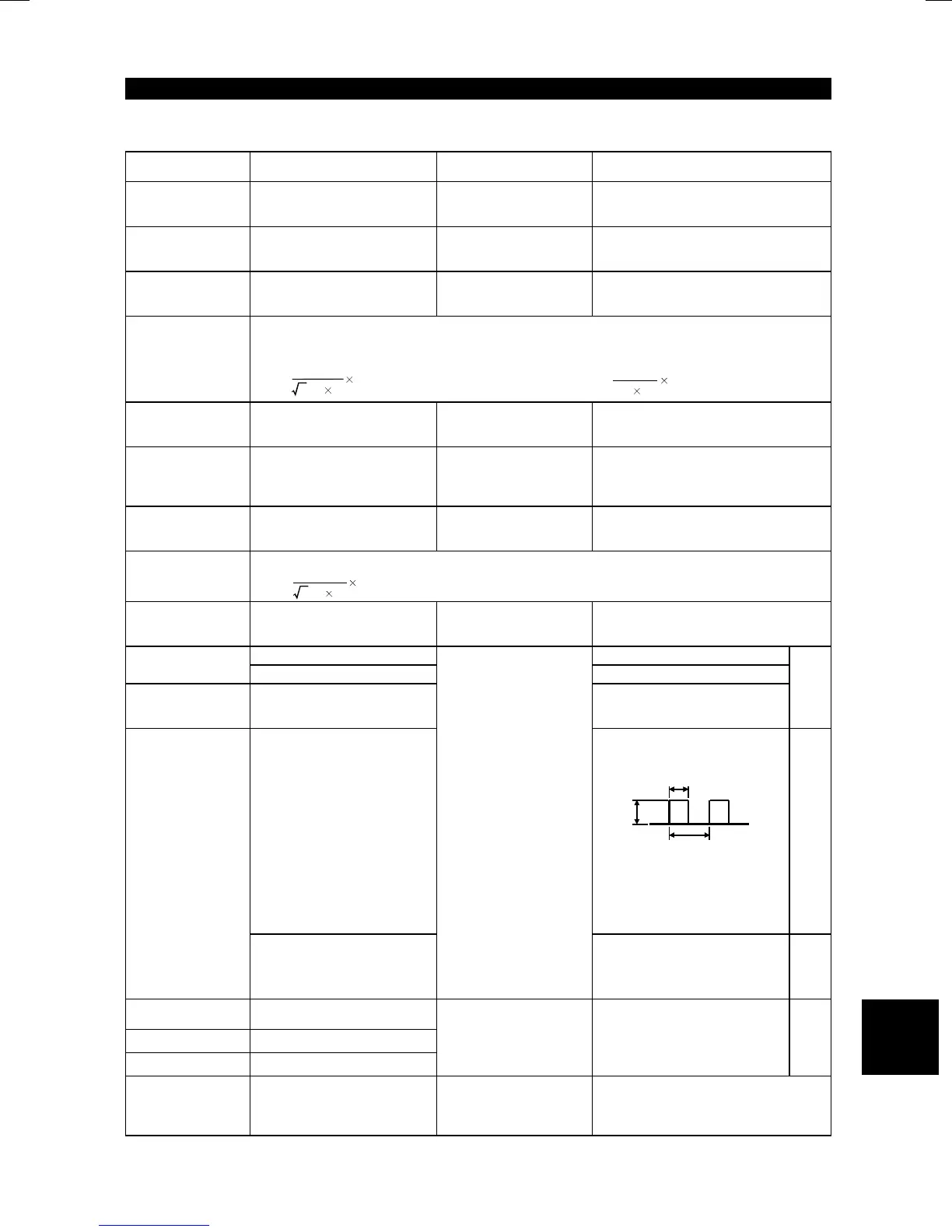
Across FM (positive)-SD
Approximately 5VDC at
maximum frequency (without
frequency meter)
8VDC
T1
T2
Pulse width T1:
Adjusted with Pr. 900
Pulse cycle T2:
Set with Pr. 55
(Valid for frequency monitor-
ing only)
SD is common.
Frequenc
meter
signal
Across AM (+
)
-5
Moving-coil type
(Meter, etc. may be
used)
(Internal resistance:
50k
Ω
or larger)
Approximately 10DVC at
maximum frequency (without
frequency meter)
"5" is
common.
Start signal
Select signal
Across STF, STR, RH, RM,
RL, MRS, RES-SD
Reset Across RES (positive)-SD
Output stop Across MRS (positive)-SD
Moving-coil type
(Meter, etc. may be
used)
(Internal resistance:
50k
Ω
or larger)
20 to 30VDC when open.
ON voltage: 1V or less
SD is
common.
Alarm signal
Across A-C
Across B-C
Moving-coil type
(such as a meter)
Continuity check
<Normal> <Fault>
Across A-C:
Discontinuity Continuity
Across B-C:
Continuity Discontinuity
5

 Loading...


