INSTALLATION AND WIRING
34
2.3 Other Wiring
2.3 Other Wiring
2.3.1 Power supply harmonics
Power supply harmonics may be generated from the converter section of the inverter,
affecting the power supply equipment, power capacitor, etc. Power supply harmonics
are different in generation source, frequency band and transmission path from radio
frequency (RF) noise and leakage currents. Take the following counter measures.
"
""
"
The differences between harmonics and RF noises are indicated below:
Item Harmonics RF Noise
Frequency
Normally 40th to 50th
degrees, (up to 3kHz) or less
High frequency (several 10kHz to MHz
order)
Environment
To wire paths, power
impedance
Across spaces, distance, laying paths
Quantitative
understanding
Logical computation is
possible
Occurs randomly, quantitative
understanding is difficult.
Generated amount
Approximately proportional
to load capacity
According to current fluctuation rate
(larger with faster switching)
Immunity of affected
device
Specified in standards for
each device.
Differs according to maker's device
specifications.
Examples of
safeguard
Install a reactor. Increase the distance.
"
""
"
Countermeasures
The harmonic current generated from the
inverter to the power supply differs
according to various conditions such as the
wiring impedance, whether a power factor
improving reactor is used or not, and output
frequency and output current on load side.
For the output frequency and output current,
the adequate method is to obtain them
under rated load at the maximum operating
frequency.
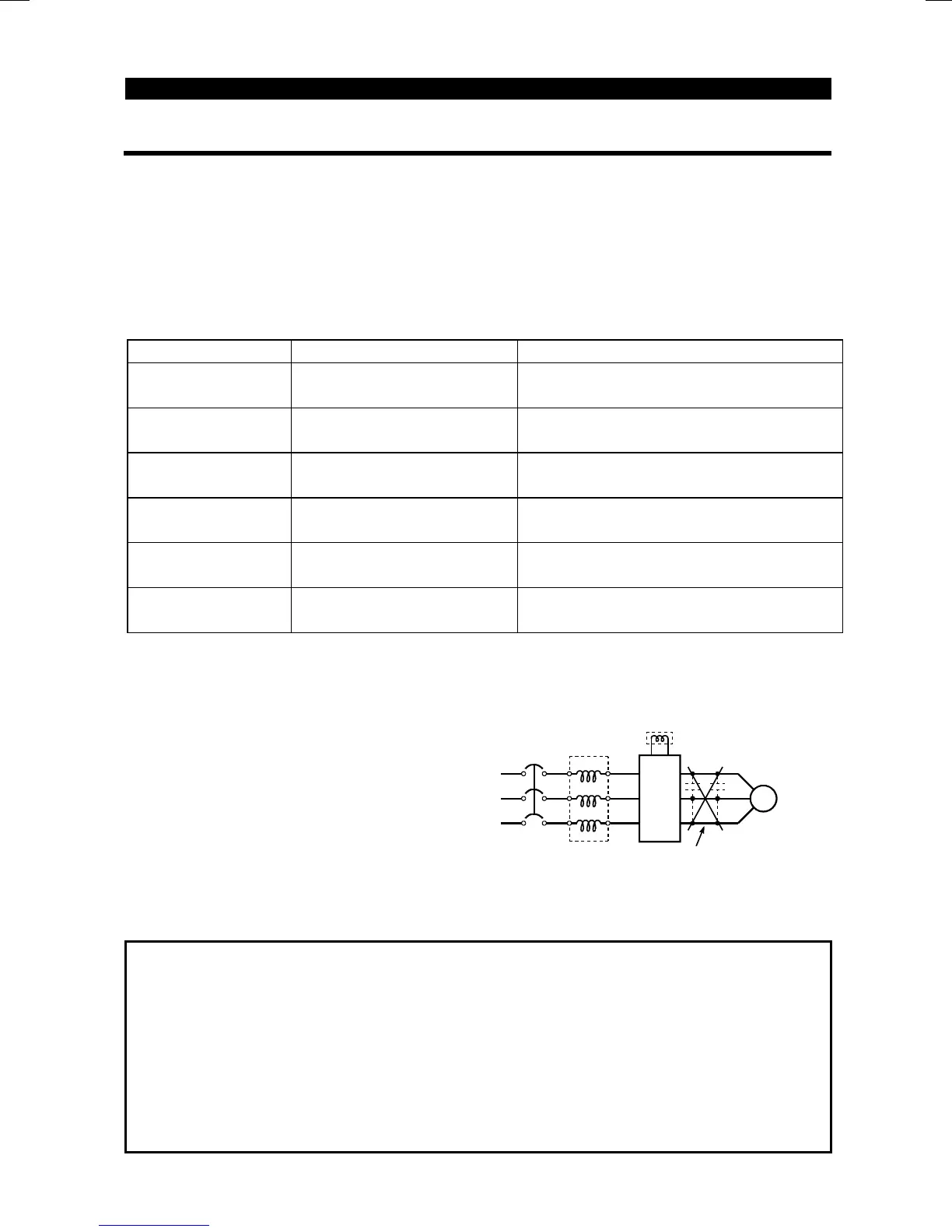
Note: A power factor improving capacitor and surge suppressor on the inverter's
output side may overheat or be damaged due to the harmonics of the inverter
output. Also, when an overcurrent flows in the inverter, the overcurrent
protection is activated. Hence, when the motor is driven by the inverter, do
not install a capacitor or surge suppressor on the inverter's output side. To
improve the power factor, insert a power factor improving reactor in the
inverter's input or DC circuit. For details, refer to the FR-A500/E500 series
technical information
NFB
IM
Power factor
improving AC
reactor
Inverter
Power factor
improving DC
reactor
Motor
Do not insert power
factor improvin
capacito

 Loading...


