© MOOG 2019
This document is subject to MOOG INTELLECTUAL AND PROPRIETARY INFORMATION LEGEND . The details are on page II.
1-6. ELECTRICAL INSTALLATION
1-6-1. GENERAL
Electrical installation includes several phases of work:
A) mounting the DigiPackⅢ in a suitable location
B) determining the correct phasing so the servovalve, tooling position transducer and, possibly,
accumulator position transducer may be connected to the DigiPackⅢ
C) determining the blow molding machine interface interaction with the DigiPackⅡand then
wiring the machine-DigiPackⅢ interface
D) connect the DigiPackⅢ to electrical power supply from the stable 24VDC
DigiPackⅢ MOUNTING
The DigiPackⅢ must be mounted in a location free of vibration, with protection from the environment and
most important, located in a position allowing the operator and setup man easy visual and physical access.
It is recommended that the mounting be on a swing out panel allowing easy access to the front and back
sides of the DigiPack3.
Mounting information is shown in “Figure 1-17”. Brackets providing simple panel mounting are included.
All wiring from the DigiPackⅢ must be shielded. The shield is to be grounded to the DigiPackⅢ
ground at the DigiPackⅢ only Any other ground paths may cause damage.
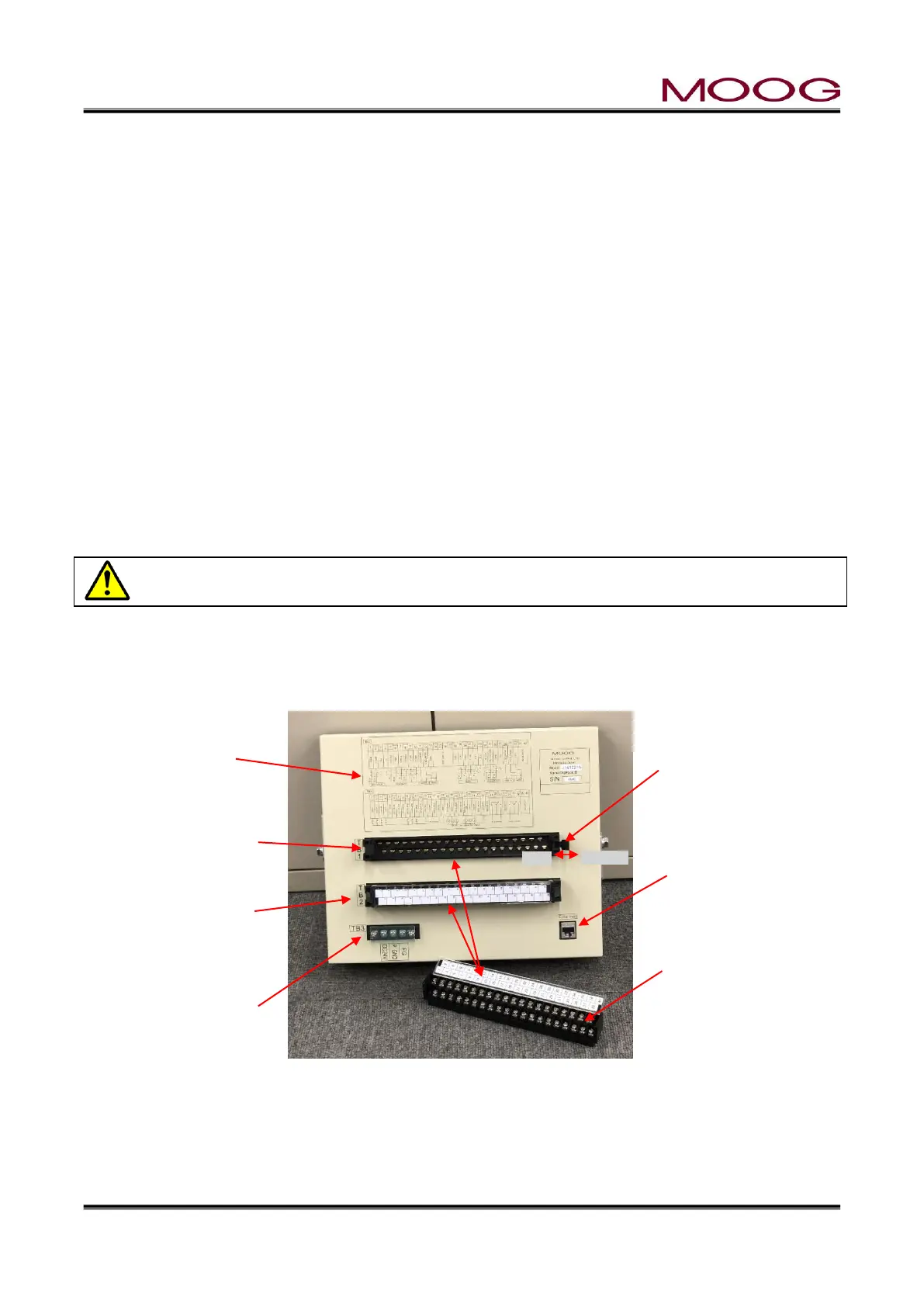
1-6-2. REAR CONNECTOR
The rear connector of DigiPackⅢ can be detached. When installing the connector, secure with the lock
lever. See Figure 1-16.
Figure 1-16 REAR CONNECTOR
Lock lever
Please lock securely
when fixing the con-
nector.
TB-3:Power connector
(Screw diameter 3.0 mm,
tightening torque 0.6 Nm)
Connector removal status
(Screw diameter 3.5 mm,
tightening torque 1.0 Nm)
TB-2 : Connector
installation state

 Loading...