© MOOG 2019
This document is subject to MOOG INTELLECTUAL AND PROPRIETARY INFORMATION LEGEND . The details are on page II.
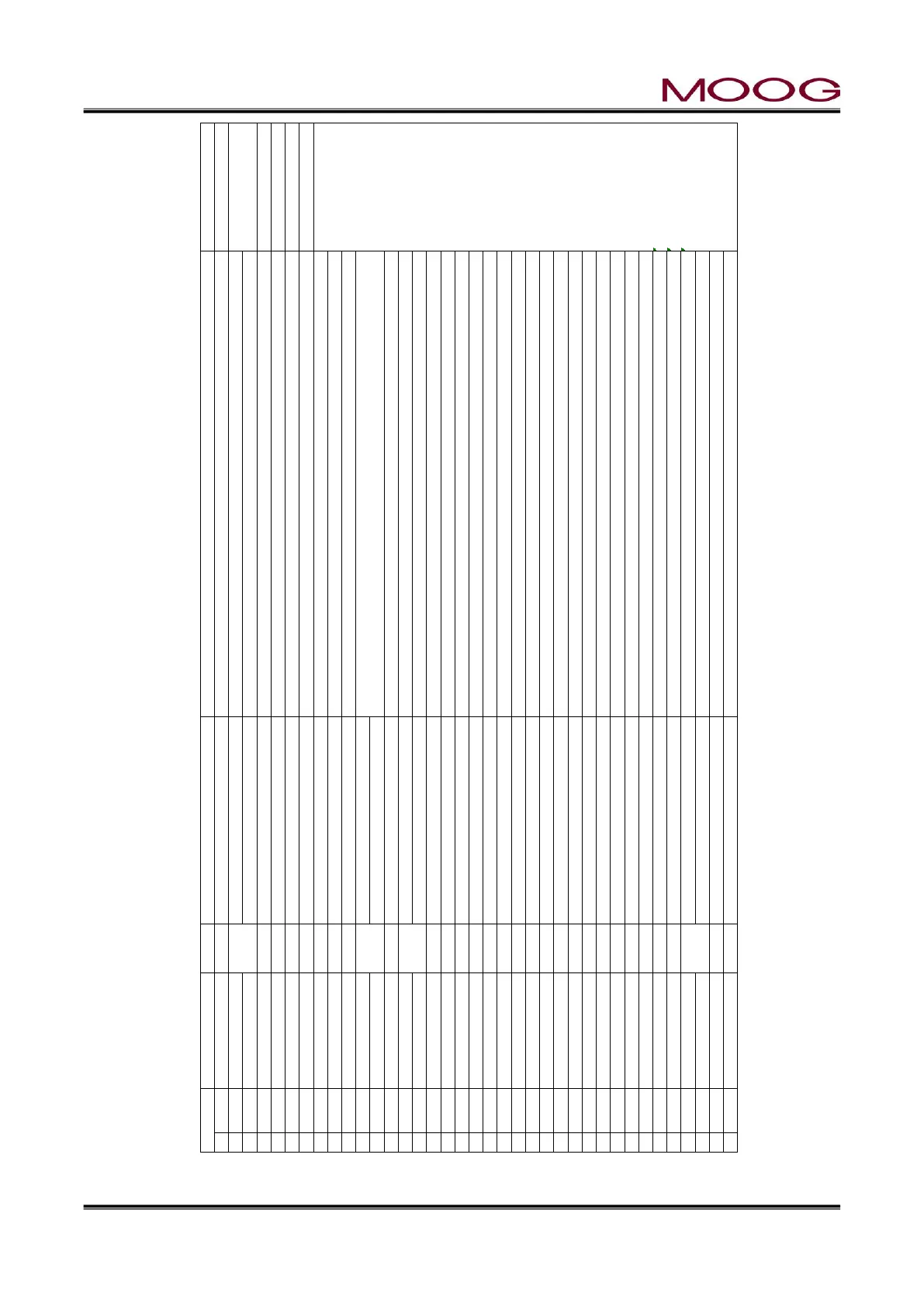
Figure 1-20 TB-1 Functions
Name IN/OUT Function Comments
1 -MFB Signal PinA or D, B to C, MEB Servo valve (MFB) Mechanical Feedback
2 +MFB Signal PinA or D, B to C, MEB Servo valve Connection A to D or D to A allow phase reversal
3 F GND(Cable Shield) Cable Shield ground, MFB Servo valve Do not ground the shield at the servovalve
4 F GND(Cable Shield) Cable Shield ground, EFB Servo valve Do not ground the shield at the servovalve
5 24V DC OUT Pin A, EFB Servo valve (EFB )Electrical Feedback Valve Power. Max 1.5A available
6 GND OUT Pin E or D, EFB Servo valve The polarity is reversed depending on the connection of pin D / E
Connection example
7 P GND Pin B, EFB Servo valve
8 EFB Signal OUT Pin D or E, EFB Servo valve EFB Signal : ±10V OUT
9 Valve Spool(-) Pin C, EFB Servo valve 1 A
10 Valve Spool(+) Pin F, EFB Servo valve 2 D
3 Shield
11 Monitor 1 Monitor Out 1 ±10 V DC OUT. Signal selectable
12 Monitor 2 Monitor Out 2 ±10 V DC OUT. Signal selectable
13 GND Monitor Ground Ground for Monitor 1 and 2 5 A
14 NOT USE 7 B
15 NOT USE 9 C
16 NOT USE 8 D
17 NOT USE 6 E
10 F
18 GND 4 Shield
19 DCDT IN (+) IN Pin C or D : DCDT Feedback signal (+) (DCDT) Parison core position feed back sensor
20 +10V DC OUT Pin A : DCDT Power voltage (+10V) The level of the feedback signal changes depending on the type of DCDT (maximum: ± 10 V)
21 DCDT IN (-) IN Pin D or C : DCDT Feedback signal (-) The polarity is reversed depending on the connection of pin C / D 20 A
22 -10V DC OUT Pin B : DCDT Power voltage (-10V) 22 B
23 F GND(Cable Shield) Cable Shield ground, DCDT Do not ground the shield at the Actuator or DCDT 19 C
21 D
24 ACC IN IN Pin 2, Potentiometer (ACC Pot) Accumulator position feed back sensor 23 Shield
25 ACC VLT OUT Pin 1 or 3, Potentiometer Available accumulator type: Internal resistance 1 kΩ or more
26 GND Pin 3 or 1, Potentiometer
27 F GND(Cable Shield) Cable Shield ground, Accumulator Do not ground the shield at the Accumulator 25 1
24 2
28 Monitor 3 Monitor Out 3 ±10 V DC OUT. Signal selectable 26 3
29 Monitor 4 Monitor Out 4 ±10 V DC OUT. Signal selectable 27 Shield
30 GND Monitor Ground Ground for Monitor 3 and 4
TB-1: Analog I/O Terminals (Moog Production and Transducers)
 Loading...