© MOOG 2019
This document is subject to MOOG INTELLECTUAL AND PROPRIETARY INFORMATION LEGEND . The details are on page II.
2-4-7. SHIFT→F1: Set Up Mode
The mode to shift by pressing [SHIFT] and pressing the [F1]
key with the [SHIFT] key active.
Display
Not available when manufacturing containers. And Produc-
tion can not be started while this screen is displayed.
Function
Set Up is used to set up the conditions and parameters re-
quired for proper operation when the container and/or die
gap tooling are changed.
Commands
Set Up Mode is covered in detail in the DigiPackⅢ Installa-
tion manual at 1-9-3. SET UP PROCEDURE.
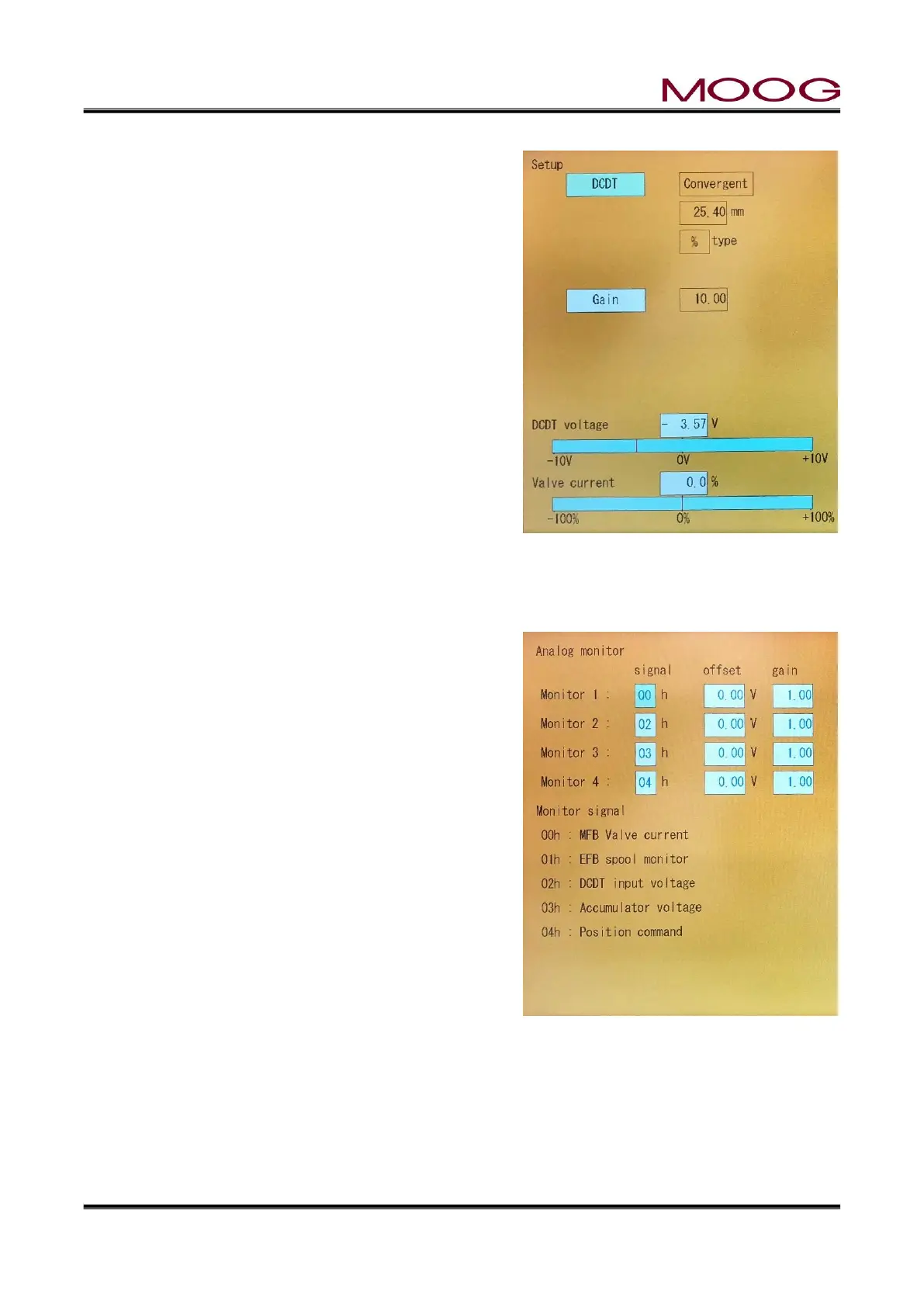
Figure 2-33 [SHIFT]→[F1]: Setup
Screen
2-4-8. SHIFT→F2: Analog monitor
The mode to shift by pressing [SHIFT] and pressing the [F2]
key with the [SHIFT] key active.
Display
Not Available while manufacturing containers. And Produc-
tion can not be started while this screen is displayed.
Function
Internal signal assign to analog monitor channels 1 to 4.
(TB1, 11, 12, 28 and 29). See 1-6-3. for details.
Commands
Change the displayed parameter using the SET Key or di-
rectly touch the parameter, revise the value with the Entry
Knob (or ten key) and confirm with the SET Key.
Figure 2-34 [SHIFT]→[F2]: Analog Moni-
tor Screen
Signal
The following signals can be set in “signal”. After that, each channel is monitored by the monitoring channel
on TB1.
00h : MFB valve current -> Monitored MFB Servovalve Current (Set at SHIT→F4) with +-10V.
01h : EFB spool monitor -> Monitored Spool position (4-20mA) with +-10V if EFB mode.
02h : DCDT input voltage -> Monitored DCDT Position (0-100%) with 0-10V.
 Loading...