MTS 793 Controller Hardware FlexTest GT Controller Connections
117
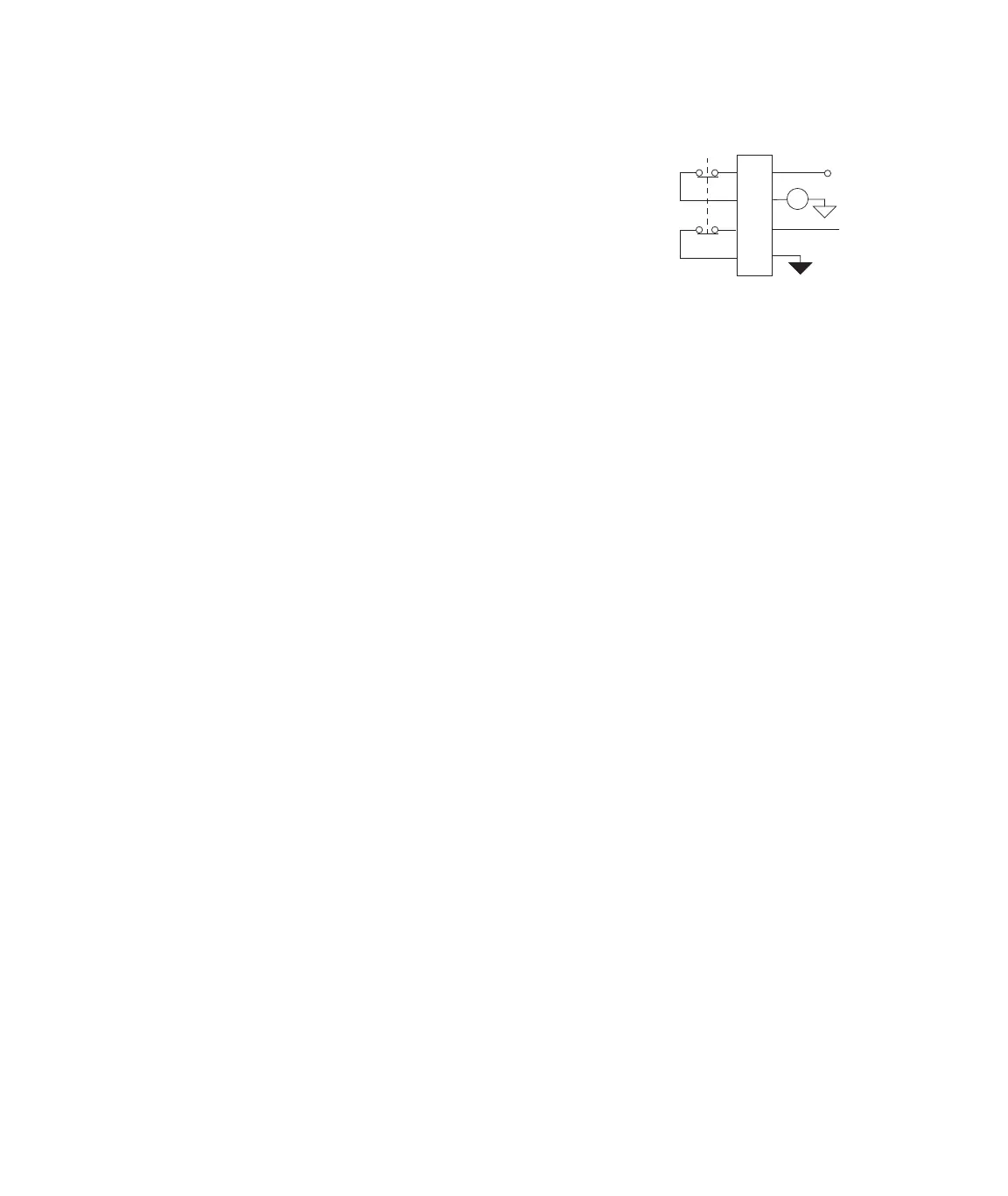
Emergency
stop input
Connector J24 E-STOP In
accommodates an external emergency
stop switch. As shown, several
connectors maintain the continuity of
the emergency stop interlock.
Cable specifications J23 E-STOP Out is a 9 pin type D male connector
• 9-contact type D female EMI connector
• Cable—24 AWG, 10 conductor with overall foil shield, (Carol
C0745 or equivalent) with drain wire connected to metallized
plastic backshell to the chassis.
J24 E-STOP In is a 15 pin type D female connector.
• 15-contact type D male EMI connector.
• Backshell–EMI metallized plastic.
• Cable–24 AWG 4 connector with overall foil shield, (Belden 9534
or equivalent) with drain wire connected to metallized plastic
backshell at the chassis and to ground at the emergency stop
station.
Jumper plug required If connector J24 is not used, you must install a jumper plug to
maintain the integrity of the interlocks. Use jumper plug PN 039-713-
201 or jumper pins: 5 and 7; 8 and 13.
+24 V
13
8
7
5
E-Stop
Signal
J24
E-Stop
Relay
External
E-Stop
Artisan Technology Group - Quality Instrumentation ... Guaranteed | (888) 88-SOURCE | www.artisantg.com
 Loading...