MTS 793 Controller Hardware
FlexTest GT Controller Connections
134
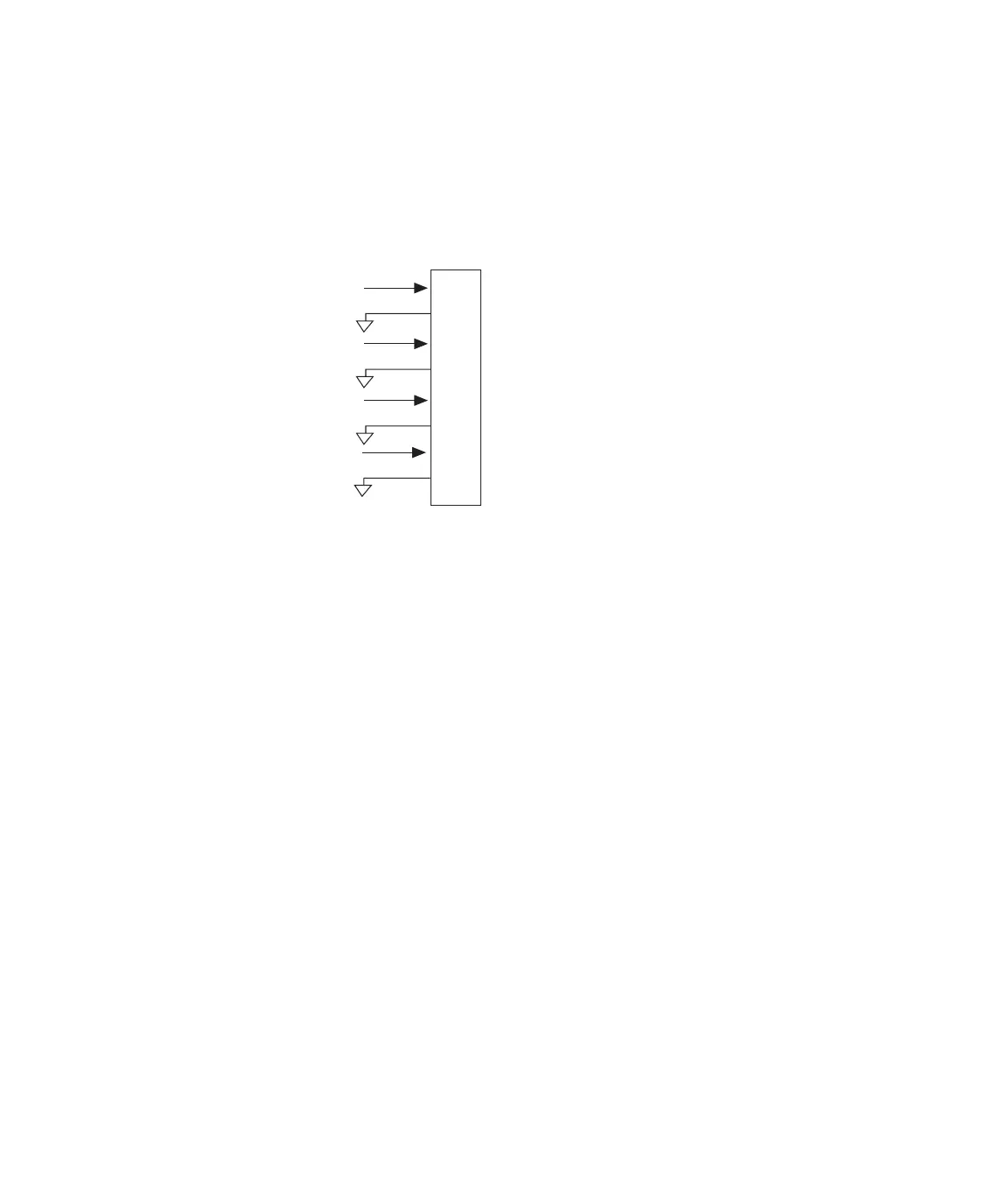
I/O Carrier service The J3 Service connector on the Model 493.40 I/O Carrier module
provides the monitor output from each of the four I/O option cards
installed. It is an 8-pin RJ-45 connector.
Important The signals at the J3 Service connector are provided for
service and troubleshooting only. These signals are defined by
the I/O option mezzanine cards that are installed on a
respective Model 493.40 I/O Carrier module. Some of these
signals may be uncalibrated. Before use, take appropriate
steps to determine the characteristics of these signals.
To
External
Device
1
2
3
4
5
6
7
8
J3
From
Daughter
Boards
Slot 1 Monitor
Slot 1 Ground
Slot 2 Monitor
Slot 2 Ground
Slot 3 Monitor
Slot 3 Ground
Slot 4 Monitor
Slot 4 Ground
Artisan Technology Group - Quality Instrumentation ... Guaranteed | (888) 88-SOURCE | www.artisantg.com
 Loading...