MTS 793 Controller Hardware
FlexTest GT Controller Connections
124
Cable specification • 9-contact type D male EMI connector.
• Backshell–EMI metallized plastic.
• Cable–shielded twisted pairs (24 AWG minimum) with drain
wire(s) connected to the metallized backshell at the chassis.
Power
characteristics
Channel inputs can be 3 volts (minimum) and 26 volts (maximum)
from an external voltage source.
Jumper plug If connector J43 is not used, you must install a jumper plug to
maintain the integrity of the interlocks. Use jumper plug PN 100-007-
948 or jumper pins 1 and 2; 3 and 4; 5 and 6; 7 and 8.
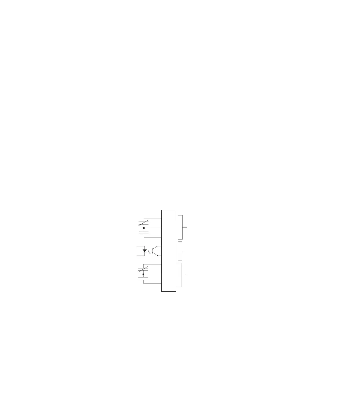
J44 Run/Stop
Run/Stop status Connector J44 Run/Stop provides the run/stop status of the controller
to external devices.
• Two form C contacts provide the run/stop status.
• The contacts are rated 1.0 A at 30 V (AC or DC).
Interlock status Connector J44 Run/Stop also provides opto-isolator outputs that
indicate the interlock status of each station to an external device.
These interlock status outputs are normally on and will turn off when
an interlock occurs. See “Digital outputs” on page 128 for detailed
circuit drawings.
Run/Stop 1
+
-
Interlock Status
Output
1
2
3
4
5
6
7
8
Run/Stop 0
J44 To
External Devices
From
Chassis
Artisan Technology Group - Quality Instrumentation ... Guaranteed | (888) 88-SOURCE | www.artisantg.com
 Loading...