MTS 793 Controller Hardware
Installing the 493.10 Chassis (FTGT)
Installation
42
Setting I/O Carrier
addresses
Use the dipswitch (S1) and rotary dipswitch (S2) on each I/O Carrier
module to set its address in accord with its installed chassis slot as
follows:
BFL
CPU
PMC
ABT
RST
J6 I/O
J7 I/O
493.40
I/O Carrier
J3 Service
Shunt Cal
J4 I/O
J5 I/O
m
CLOCK OUT
EVENT OUT
J3 IN
J6 STATION
J7 SERIAL
EVENT IN
J4 OUT
J5 DEBUG
+12V
12345678910
BFL
CPU
PMC
ABT
RST
J6 I/O
J7 I/O
J6 I/O
J7 I/O
J6 I/O
J7 I/O
J6 I/O
J7 I/O
J6 I/O
J7 I/O
J6 I/O
J7 I/O
493.40
I/O Carrier
J3 Service
Shunt Cal
J4 I/O
J5 I/O
m
493.40
I/O Carrier
J3 Service
Shunt Cal
J4 I/O
J5 I/O
m
493.40
I/O Carrier
J3 Service
Shunt Cal
J4 I/O
J5 I/O
m
493.40
I/O Carrier
J3 Service
Shunt Cal
J4 I/O
J5 I/O
m
493.40
I/O Carrier
J3 Service
Shunt Cal
J4 I/O
J5 I/O
m
493.40
I/O Carrier
J3 Service
Shunt Cal
J4 I/O
J5 I/O
m
m
498.98-2
Power PC
m
498.98-2
Power PC
m
498.71B
GRES III
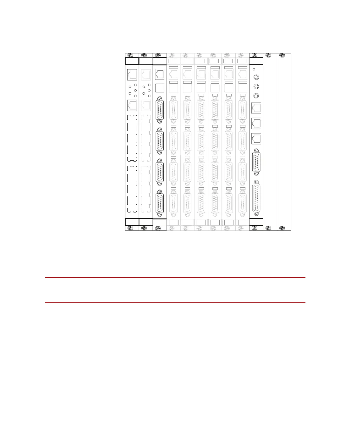
P
acement o
VMEbus modules in
the front panel
chassis
S
LOT
12345678910
ADDRESS
PPC C20 C22 C24 C26 C28 C2A C2C C2E
Artisan Technology Group - Quality Instrumentation ... Guaranteed | (888) 88-SOURCE | www.artisantg.com
 Loading...